Connecting the board for i/o operations, Connectors, cables – main i/o connector, Pin out – main i/o connector – Measurement Computing PCI-DIO24H User Manual
Page 10
PCI-DIO24H User's Guide
Installing the PCI-DIO24H
10
Connecting the board for I/O operations
Connectors, cables
– main I/O connector
The table below lists the board connector type, applicable cables, and compatible accessory products for the
PCI-DIO24H.
Board connectors, cables, and accessory equipment
Connector type
37-pin D-type
Compatible cables
C37FF-x unshielded ribbon cable. x = length in feet. (see Figure 2)
C37FFS-x shielded round cable. x = length in feet. (see Figure 3)
Compatible accessory products with the
C37FF-x or C37FFS-x cable
SCB-37
CIO-MINI37
CIO-MINI37-VERT
CIO-ERB08
CIO-SERB08
CIO-ERB24
CIO-SPADE50
SSR-RACK08
SSR-RACK24
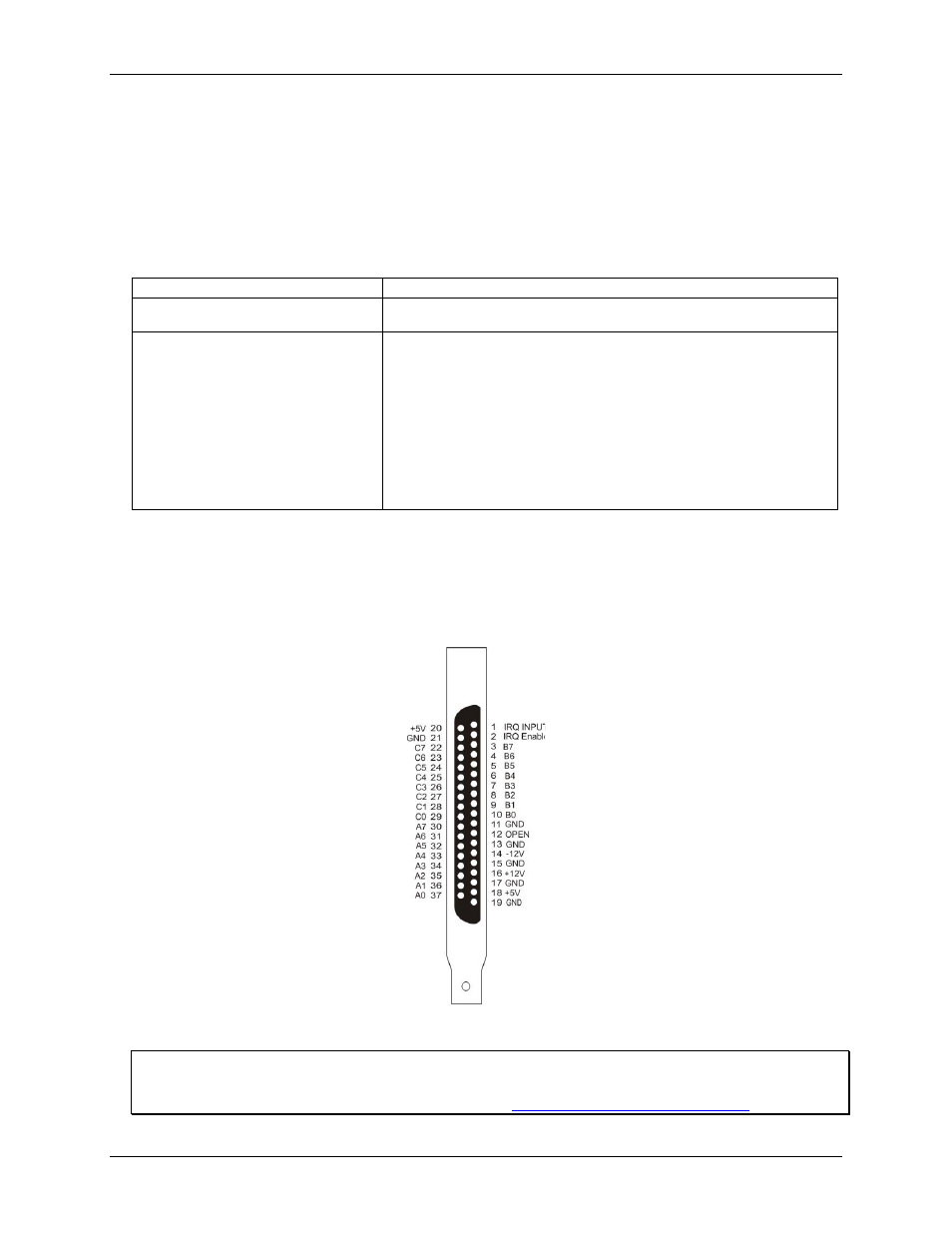
Pin out
– main I/O connector
The I/O connector is a 37-pin, male D-type connector accessible from the rear of the computer through the
expansion backplate. The signals available are direct connections to the digital I/O chips as well as the
computer's internal power supplies. The pin out is identical to the CIO-DIO24, except that –5 VDC is not
brought out. The PCI-DIO24H board's I/O connector is shown in Figure 1.
Figure 1. PCI-DIO24H board connector pin out
Information on signal connections
General information regarding signal connection and configuration is available in the Guide to Signal
Connections. This document is available on our web sit