0 hardware installation – Measurement Computing PC104-DI48 User Manual
Page 6
3.0 HARDWARE INSTALLATION
3.1 BOARD SETUP
The PC104-DI48 is setup at the factory with BASE ADDRESS= 300h (768 decimal).
Open your PC (after turning off the power) and install the board. Leave the address
switches as they were set at the factory or refer to the information below to change the
settings. After the board is installed and the computer is closed up, turn power on.
PC104-DI48 is a dedicated 48 line digital input board built up of logic chips. There
are no control registers. The input pins present a single LSTTL load.
3.2 BASE ADDRESS
The PC104-DI48 employs the PC bus for power, communications and data transfer.
As such, it draws power from the PC, monitors the address lines and control signals
and responds to it's I/O address. It receives and places data on eight data lines.
Base address is the most important user-selectable item of the PC104-DI48. The base
address is the starting location that software reads from when communicating with the
PC104-DI48. DIP switches (Figures 3-1 and 4-2) are used to set the base address (0).
Each switch position corresponds to one of the PC bus address lines. By placing the
switch down, the address decode logic adds that value to the base address.
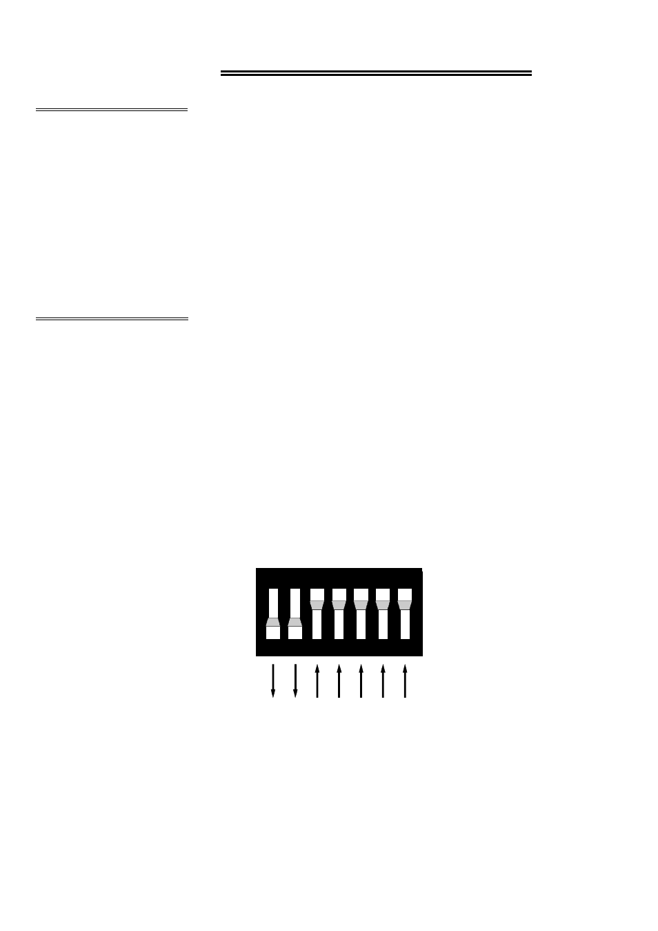
A base address is constructed by
calculating the HEX or decimal
number which will be the address
the board will respond to. For
example, in Figure 3-1, switches 1
and 2 are down, all others are up.
Switch 1 = 200h (512d) and switch
2 = 100h (256d). Added together
they equal 300h (768 decimal).
Figure 3-1. Base Address Switches (300h Shown)
Certain addresses are used by the PC, others are free and may be used by the
PC104-DI48 and other expansion boards. We recommend that BASE = 300h (768D)
be tried first. Refer to Table 3-1 below for PC I/O addresses.
2
S W H E X
1
2 0 0
2
1 0 0
3
8 0
4
4 0
5
2 0
6
1 0
7
0 8
1 2 3 4 5 6 7