Wait state jumper, Individual / simultaneous transfer jumper – Measurement Computing CIO-DDA06 User Manual
Page 10
CIO-DDA06 User's Guide
Installing the CIO-DDA06
SW
A9
A8
A7
A6
A5
A4
HEX
200
100
80
40
20
10
ADDRESS
9
8
7
6
5
4
Figure 1. Base address switch
In the default configuration shown in Fi
, addresses 9 and 8 are DOWN, and all others are UP.
Address 9
= 200 hex (512 decimal), and address 8 = 100 hex (256 decimal). When added together they equal
300 hex (768 decimal).
Disregard the numbers printed on the switch
When setting the base address, refer to the numbers printed in white on the printed circuit board.
Wait state jumper
The CIO-DDA06 board has a wait state jumper which you can set to enable an on-board wait state generator. A
wait state is an extra delay injected into the processor's clock via the bus. This delay slows down the processor
when the processor addresses the CIO-DDA06 board so that signals from slow devices (chips) will be valid.
configured for OFF (wait state is disabled).
Figure 2. Wait State jumper
ON
OFF
The wait state generator on the CIO-DDA06 is only active when the CIO-DDA06 is being accessed. Your PC
will not be slowed down in general by using the wait state.
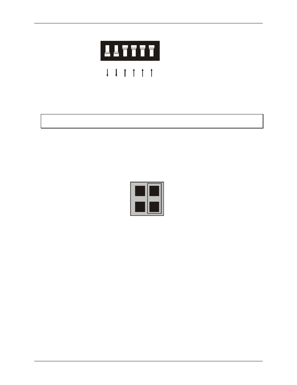
Individual / simultaneous transfer jumper
The analog outputs can be jumpered so that new output data is held until several DACs have been loaded with
new digital data. Then, as a group, the data for each DAC is simultaneously transferred and the DAC voltage
outputs are updated when any of the addresses BASE + 0 to BASE + B are read.
The analog output chips on the CIO-DDA06 are dual DACs (two analog outputs per chip). Each DAC channel
pair has an associated jumper that sets both DACs on a single chip to be either simultaneously transferred on a
read, or individually updated when the control register is written.
Figure 3 shows the jumper block configured for each update mode. Two numbers are listed on the board next to
each simultaneous transfer jumper (45, 23, and 01 from left to right). The numbers indicate which channel pair
is configured by the jumper (channels 0 and 1, 2 and 3, 4 and 5).
10