Analog output range switch, Installing the cio-dda06/16 – Measurement Computing CIO-DDA06/16 User Manual
Page 11
CIO-DDA06/16 User's Guide
Installing the CIO-DDA06/16
Analog output range switch
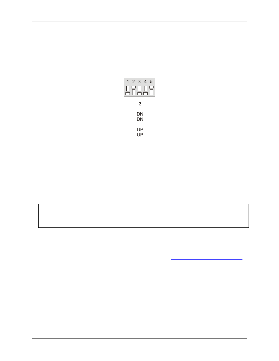
The analog output voltage range of each channel can be set with a set of five-position DIP switches. The switch
blocks are located on the board below the calibration potentiometers. The switch blocks are labeled
S1
to
S6
,
and individual switches are labeled
1
through
5
. Set the switches for each individual channel as shown in
Figure 4. Analog output range switch — one per DAC — configured for ±5 V
Range
10 V
5.0 V
0-10 V
0-5 V
±
±
1
DN
DN
UP
UP
2
UP
UP
DN
DN
4
UP
DN
UP
DN
5
DN
UP
DN
UP
(Shown)
Sx
To set a channel to a particular range, read the switch positions as UP or DN (down) from left to right in the
row beside the range you want to set. The switch shown in Fi
is configured for ±5V range (switch
settings DN>UP>DN>DN>UP).
Installing the CIO-DDA06/16
After you configure the board's switches and jumpers, you can install the CIO-DDA06/16 into your computer.
To install your board, follow the steps below.
Install the MCC DAQ software before you install your board
The driver needed to run your board is installed with the MCC DAQ software. Therefore, you need to install
the MCC DAQ software before you install your board. Refer to the Quick Start Guide for instructions on
installing the software.
1.
2.
3.
Turn your computer off, open it up, and insert your board into an available ISA slot.
Close your computer and turn it on.
To test your installation and configure your board, run the InstaCal utility you installed in the previous
section. Refer to the Quick Start Guide that came with your board
for information on how to initially set up and load InstaCal.
1