Individual / simultaneous transfer jumper – Measurement Computing CIO-DDA06/16 User Manual
Page 10
CIO-DDA06/16 User's Guide
Installing the CIO-DDA06/16
SW
A9
A8
A7
A6
A5
A4
HEX
200
100
80
40
20
10
9
8
7
6
5
4
ADDRESS
Figure 2. Base address switch
In the default configuration shown in Fi
, addresses 9 and 8 are DOWN, and all others are UP.
Address 9
= 200 hex (512 decimal), and address 8 = 100 hex (256 decimal). When added together they equal
300 hex (768 decimal).
Disregard the numbers printed on the switch
When setting the base address, refer to the numbers printed in white on the printed circuit board.
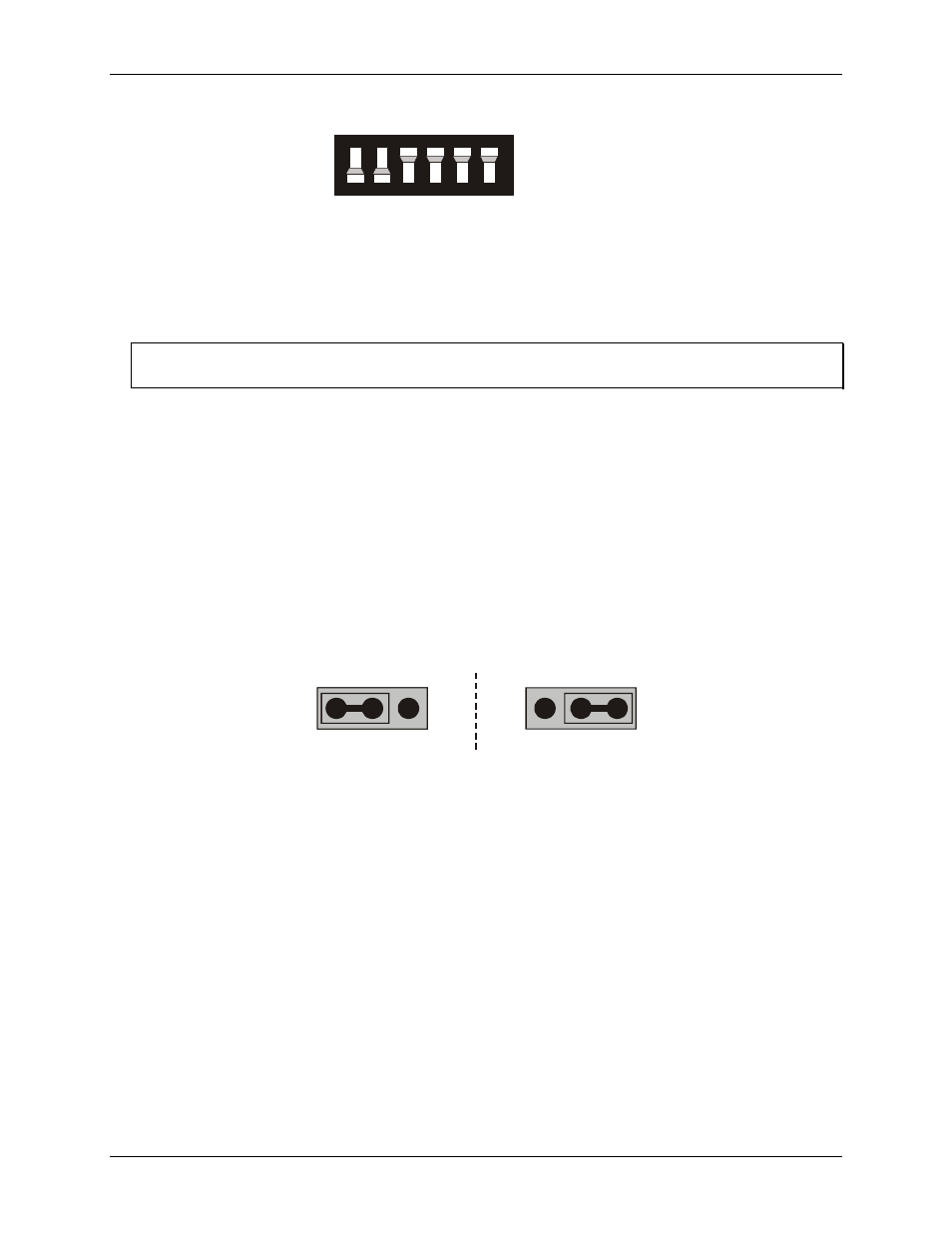
Individual / simultaneous transfer jumper
The analog outputs can be jumpered so that new output data is held until several DACs have been loaded with
new digital data. Then, as a group, the data for each DAC is simultaneously transferred and the DAC voltage
outputs are updated when any of the addresses BASE + 0 to BASE + B are read.
The analog output chips on the CIO-DDA06/16 are dual DACs (two analog outputs per chip). Each DAC
channel pair has an associated jumper that sets both DACs on a single chip to be either simultaneously
transferred on a read, or individually updated when the control register is written.
Figure 3 shows the jumper block configured for each update mode. Two numbers are listed on the board next to
each simultaneous transfer jumper (45, 23, and 01 from left to right). The numbers indicate which channel pair
is configured by the jumper (channels 0 and 1, 2 and 3, 4 and 5).
Individual updates
per channel
XFER
UPDATE
J1
Simultaneous updates
of both channel
XFER
UPDATE
J1
Figure 3. Individual / simultaneous update jumper
When the jumpers are in the
XFER
position, new output data is held until one or more DACs have been
loaded with new digital data. The new data transfers to the voltage outputs as a group. The simultaneous
transfers occur when any of the CIO-DDA06/16 addresses are read (and the jumpers are in the
XFER
position).
When the jumpers are in the
UPDATE ##
position, the DAC channel pair is individually updated when the
control register is written.
1