Field wiring, signal termination, and conditioning, Field, Wiring, signal termination, and conditioning – Measurement Computing CIO-DAS801 User Manual
Page 14
CIO-DAS801 User's Guide
Installing the CIO-DAS801
14
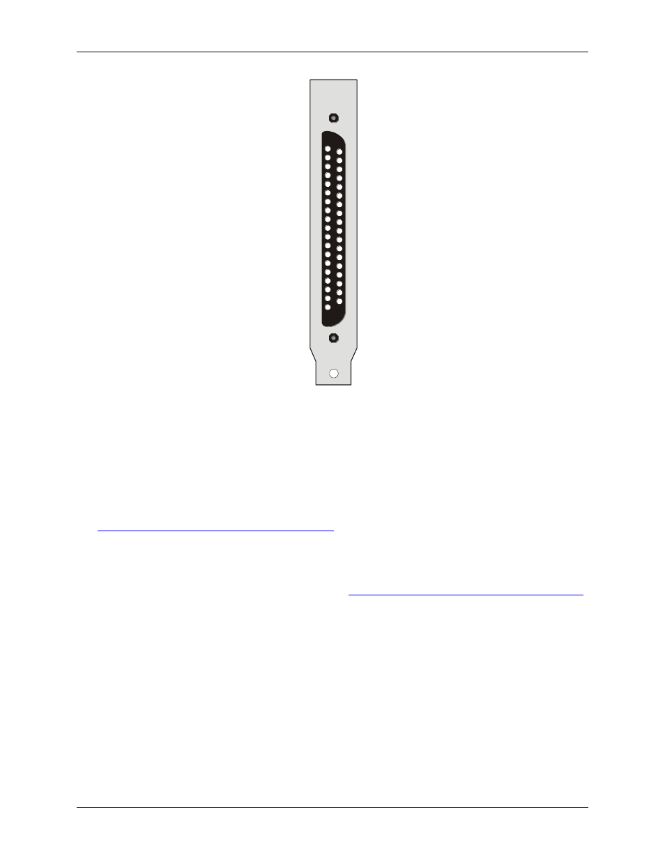
37 CH0 HI
36
35
34
33
32
31
30
29 PC +5
28 DGND
27 DIN3
26 DIN2
25 DIN1 / Trig
24 IR Input / XCLK
23 CTR2 Gate
22 CTR1 Gate
21 CTR0 Gate
20 -15V From DC/DC
CH1 HI
CH2 HI
CH3 HI
CH4 HI
CH6 HI
CH7 HI
CH8 HI
CH0 LO 19
CH1 LO 18
CH2 LO 17
CH3 LO 16
CH4 LO 15
14
13
12
LLGND 11
DOUT4 10
3 9
2 8
1 7
CTR2 Out 6
CTR1 Out 5
CTR1 In 4
CTR0 Out 3
CTR0 In 2
+15V From DC/DC 1
CH5 LO
CH6 LO
CH7 LO
DOUT
DOUT
DOUT
Figure 7. I/O connector pin-out
Field wiring, signal termination, and conditioning
You can use the following cabling, screw termination, and signal conditioning products with the CIO-DAS801.
CIO-MINI37 – 37-pin screw terminal board.
CIO-TERMINAL – 37-pin screw terminal board with on-board prototyping area.
Details on these products are available on our web site at
CIO-EXP16 – 16-channel analog multiplexer board with on-board CJC sensor.
CIO-EXP32 – 32-channel analog multiplexer board with on-board CJC sensor and 2 Gain amps.
ISO-RACK08 – Isolated 8-channel, 5B module rack for analog signal conditioning and expansion.
Details on these products are available on our web sit