Input configuration – Measurement Computing CIO-DAS801 User Manual
Page 10
CIO-DAS801 User's Guide
Installing the CIO-DAS801
10
5 4 3
6
9 8 7
SW
A9
A8
A7
A6
A5
A4
A3
HEX
200
100
80
40
20
10
08
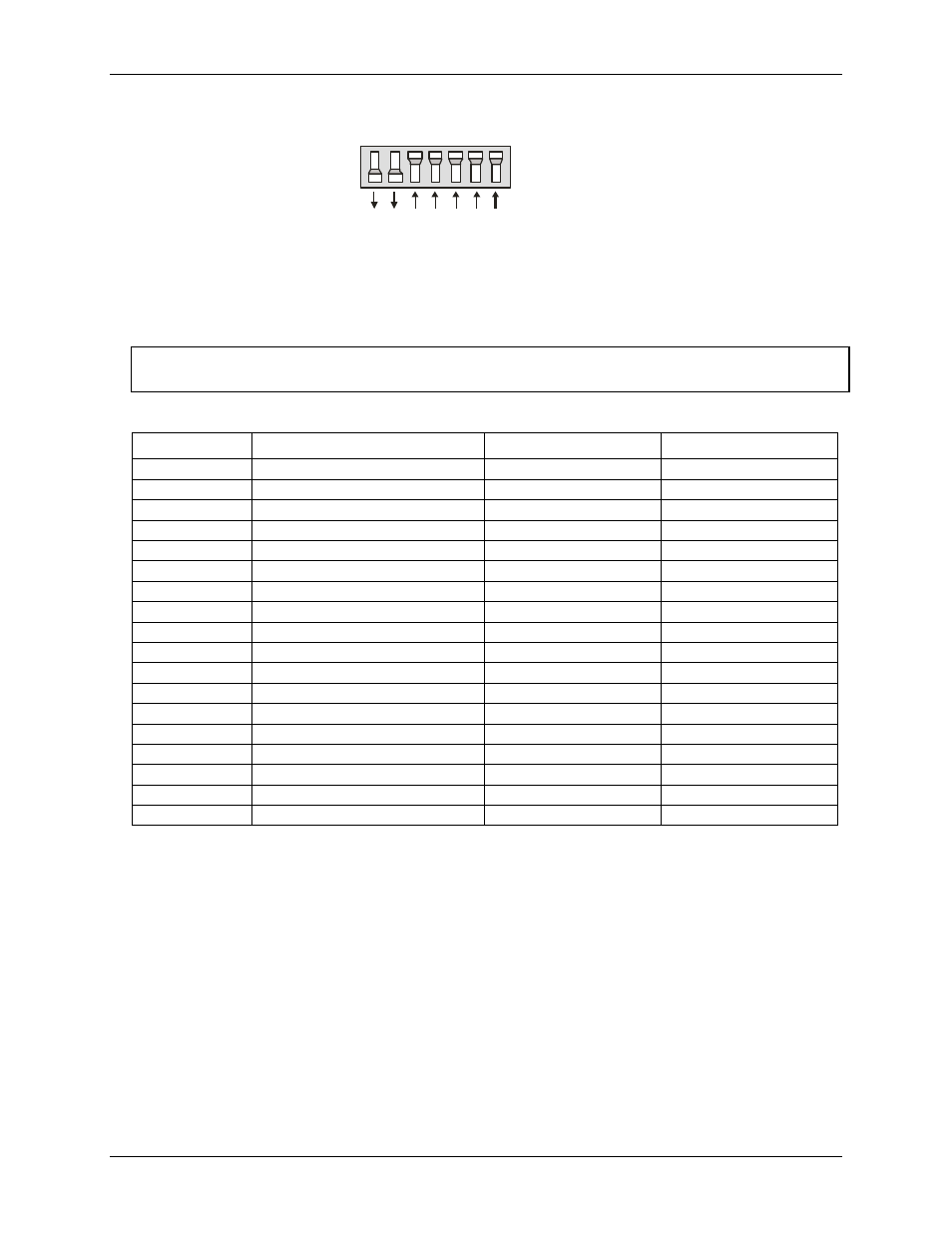
Figure 1. Base address switches
In the default configuration shown in Figure 1, addresses 9 and 8 are DOWN, and all others are UP.
Address 9 = 200 hex (512 decimal) and address 8 = 100 hex (256 decimal); when added together they equal
300 hex (768 decimal).
Disregard the numbers printed on the switch
When setting the base address, refer to the numbers printed in white on the printed circuit board.
PC I/O addresses
Hex Range
Function
Hex Range
Function
000-00F
8237 DMA #1
2C0-2CF
EGA
020-021
8259 PIC#1
2D0-2DF
EGA
040-043
8253 Timer
2E0-2E7
GPIB (AT)
060-063
8255 PPI (XT)
2E8-2EF
Serial Port
060-064
8742 Controller (AT)
2F8-2FF
Serial Port
070-071
CMOS RAM & NMI mask (AT)
300-30F
Prototype card
080-08F
DMA page registers
310-31F
Prototype card
0A0-0A1
8259 PIC #2 (AT)
320-32F
Hard disk (XT)
0A0-0AF
NMI mask (XT)
378-37F
Parallel printer
0C0-0DF
8237 #2 (AT)
380-38F
SDLC
0F0-0FF
80287 numeric CO-P (AT)
3A0-3AF
SDLC
1F0-1FF
Hard disk (AT)
3B0-3BB
MDA
200-20F
Game control
3BC-3BB
Parallel printer
210-21F
Expansion unit (XT)
3C0-3CF
EGA
238-23B
Bus mouse
3D0-3DF
CGA
23C-23F
ALT bus mouse
3E8-3EF
Serial port
270-27F
Parallel printer
3F0-3F7
Floppy disk
2B0-2BF
EGA
3F8-3FF
Serial port
Input configuration
You can configure each analog channel for differential or single-ended input. You can set the input of each
channel using the bank of switches labeled
S2
(0 through 7) on the board. These switches correspond to
channels 0 to 7 of the analog inputs.
The switches are set by default for differential input. Differential inputs are 3-wire analog hookups consisting
of a signal high, signal low and chassis ground. The benefits of differential inputs are the ability to reject noise
which affects both signal high and low, and the ability to compensate for ground loops or potentials between
signal low and chassis ground.
Although differential inputs are often preferable to single ended inputs, the floating nature of a differential
input can make getting an accurate reading difficult. In those cases, the CIO-DAS801 inputs can be converted
to single-ended or modified differential.