Measurement Computing CIO-DAS801 User Manual
Page 11
CIO-DAS801 User's Guide
Installing the CIO-DAS801
11
The CIO-EXP16 and CIO-EXP32 were designed to interface to a single-ended input. Failure to set the switches
to single-ended when an EXP is connected results in floating, unstable readings from the EXP.
There are two ways to configure the analog inputs:
Set the bank of eight DIP switches on the jumper block labeled S2 located near the I/O connector.
Position the switches in the OFF position (down) to configure the input for differential mode (default).
Position the switches in the ON position (up) to configure the input for single-ended mode.
0
N
4 5 6
3
0 1 2
7
S2
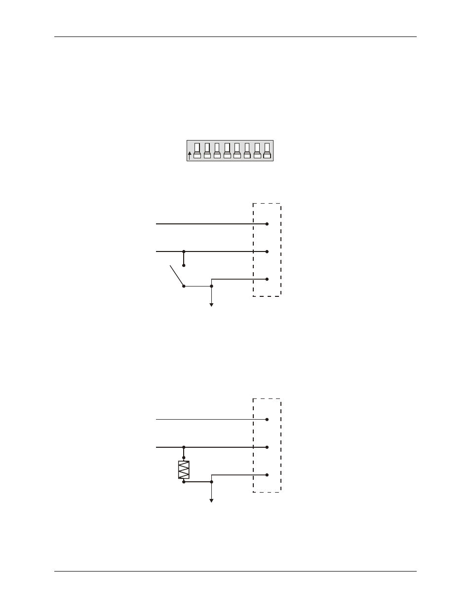
Figure 2. Input configuration jumpers
Figure 3 shows one analog input and the single-ended / differential switch.
To A/D
Circuit
CH0 HI
CH0 LO
Low Level Ground
(LLGND)
Switch for
Differential = Open
Single Ended = Closed
Figure 3. Input configuration switch
You can also install an SIP resistor pack at position RN2 to convert the inputs to single-ended.
This package of 10K resistors provides a reference to ground for each of the eight Low Input lines. This
type of input behaves like a single-ended input since there is a reference to ground and floating sources
may be measured.
Figure 4 shows one analog input line with the SIP resistor installed. When the SIP resistor package is
installed, all eight analog inputs are single-ended.
To A/D
Circuit
CH0 HI
CH0 LO
Low Level Ground
(LLGND)
Resistor SIP
Differential = RN2 Open
Single Ended = RN2 Installed
Figure 4. Analog input configuration
Note
: If you are using an EXP board with the CIO-DAS801, do not install the SIP resistor. Set the input
configuration switch to single-ended for both the EXP channel and the CJC channel.