Unpacking the cio-das08/jr, Installing the software, Configuring the cio-das08/jr – Measurement Computing CIO-DAS08/JR User Manual
Page 9
CIO-DAS08/JR User's Guide
Installing the CIO-DAS08/JR
9
Unpacking the CIO-DAS08/JR
As with any electronic device, you should take care while handling to avoid damage from static
electricity. Before removing the CIO-DAS08/JR from its packaging, ground yourself using a wrist strap or by
simply touching the computer chassis or other grounded object to eliminate any stored static charge.
If any components are missing or damaged, notify Measurement Computing Corporation immediately by
phone, fax, or e-mail:
Phone: 508-946-5100 and follow the instructions for reaching Tech Support.
Fax: 508-946-9500 to the attention of Tech Support
Email:
Installing the software
Refer to the Quick Start Guide for instructions on installing the software on the Measurement Computing Data
Acquisition Software CD. This booklet is available in PDF
Configuring the CIO-DAS08/JR
Before you install the CIO-DAS08/JR in your computer, you must set the base address by using the dip switch
labeled
ADDRESS
located on the board. By default, this address is set to 300 h (768 decimal). The easiest way
to set the base address switch is to let InstaCal show you the correct settings. However, if are already familiar
with setting ISA base addresses, you may use the base address switch description below to guide your base
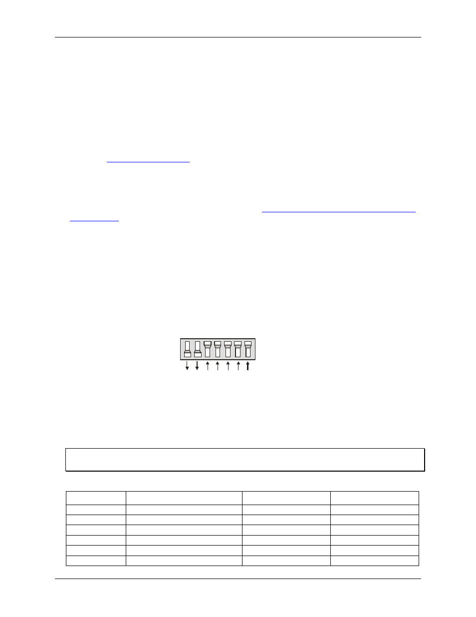
address selection. The example shown in Figure 1 shows the settings for the factory-default base address of 300
hex.
5 4 3
6
9 8 7
SW
A9
A8
A7
A6
A5
A4
A3
HEX
200
100
80
40
20
10
08
Figure 1. Base address switches
The address logic works by adding up the weights of individual switches to make up a base address. In the
default configuration shown in Figure 1, addresses 9 and 8 are DOWN, and all others are UP.
Address 9 = 200 hex (512 decimal) and address 8 = 100 hex (256 decimal); when added together they equal
300 hex (768 decimal).
Disregard the numbers printed on the switch
When setting the base address, refer to the numbers printed in white on the printed circuit board.
PC I/O addresses
Hex Range
Function
Hex Range
Function
000-00F
8237 DMA #1
2C0-2CF
EGA
020-021
8259 PIC#1
2D0-2DF
EGA
040-043
8253 Timer
2E0-2E7
GPIB (AT)
060-063
8255 PPI (XT)
2E8-2EF
Serial Port
060-064
8742 Controller (AT)
2F8-2FF
Serial Port
070-071
CMOS RAM & NMI mask (AT)
300-30F
Prototype card