Pinout – main i/o connector, Field wiring, signal termination, and conditioning – Measurement Computing CIO-DAS08/JR User Manual
Page 11
CIO-DAS08/JR User's Guide
Installing the CIO-DAS08/JR
11
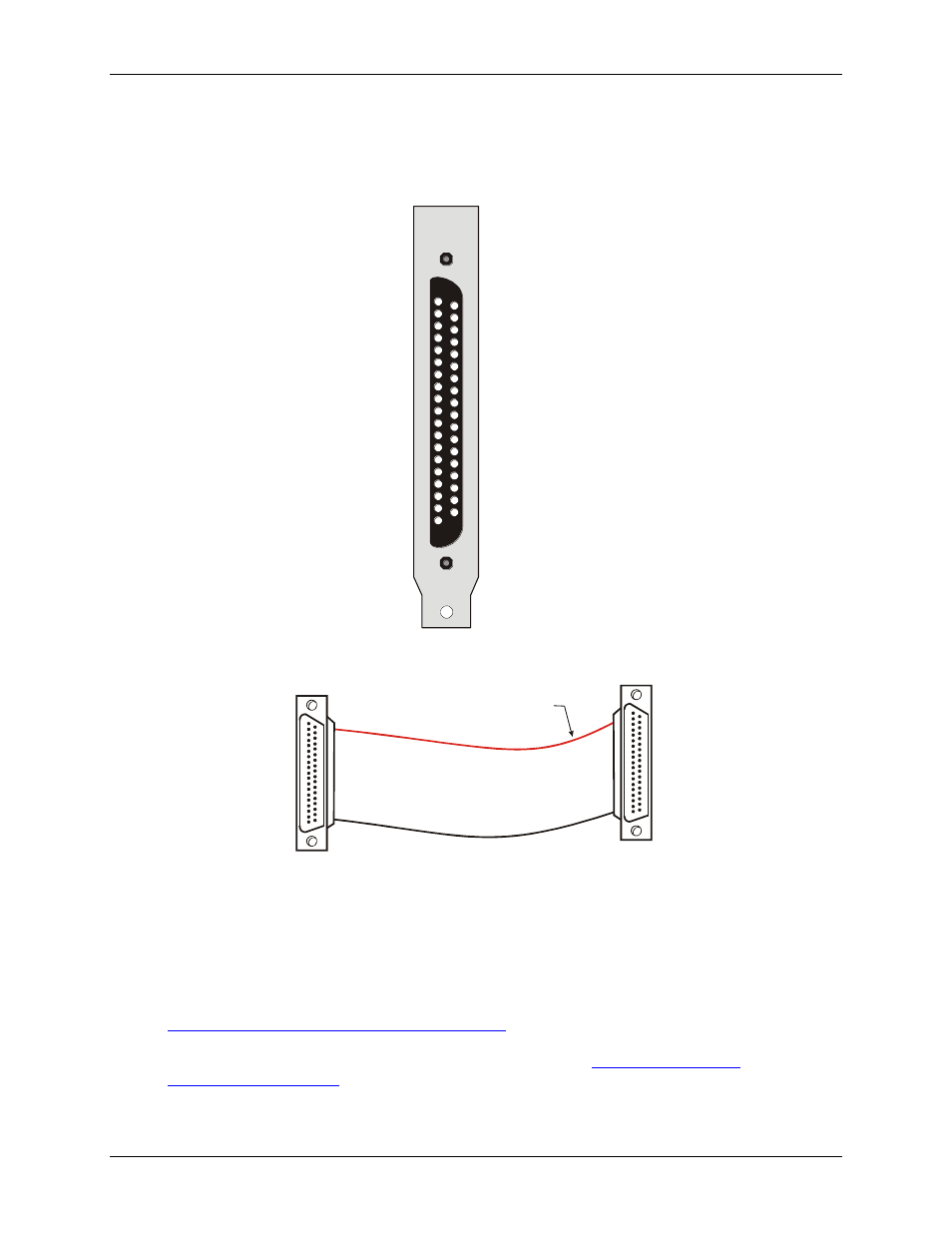
Pinout
– main I/O connector
The CIO-DAS08/JR I/O connector is a standard 37-pin male D connector that is accessible from the rear of the
computer through the expansion backplate.
37 DGND
36 DGND
35 +12V from PC bus
34 -12V from PC bus
33 5V from PC bus
32 5V from PC bus
31 D
7
30 D
6
29 DIN5
28 DIN4
27 DIN3
26 DIN2
25 DIN1
24 DIN0
23 AGND
22 AGND
21 AGND
20 AGND
IN
IN
N/C 19
N/C 18
AGND 17
DOUT7 16
DOUT6 15
5 14
4 13
3 12
2 11
1 10
0 9
CH7 IN 8
7
6
5
4
3
2
1
DOUT
DOUT
DOUT
DOUT
DOUT
DOUT
CH6 IN
CH5 IN
CH4 IN
CH3 IN
CH2 IN
CH1 IN
CH0 IN
Figure 2. CIO-DAS08/JR pin-out
20
1
37
19
20
1
37
19
The red stripe
identifies pin # 1
Female connector
Female connector
Figure 3. C37FF-x cable
Field wiring, signal termination, and conditioning
You can use the following cabling, screw termination, and signal conditioning products with the CIO-
DAS08/JR.
CIO-MINI37 – 37-pin screw terminal board. Details are available at
DFCON37 – Connector kit that includes a 37-pin female D-connector, D-shell, 37 crimp pins, and cable
termination kit to construct your own cable. Details are availa
CIO-LAB8-TERM – Experimentors Laboratory Screw Terminal Board for the DAS08 series.