Electrical system, Hydraulic system, Electrical system -4 hydraulic system -4 – MEGA Corp. MES34-OPS-1 User Manual
Page 11: System description
MES34-OPS-1
21 Feb 2014
SECTION 2
System Description
2-4
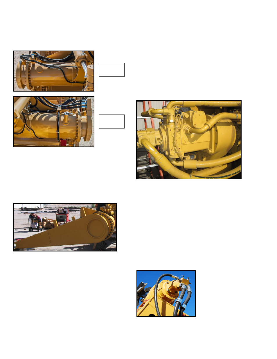
FUEL TANK
The fuel tank is constructed from a 26' mechanical
tube and two 1.5" thick flanges. The tank has a 250
gallon capacity with internal baffling to prevent
sloshing. The tank contains a fuel quantity sensor,
gravity fill port and the fast fill fuel system. The tank
also provides mounting for the draft arms,
implement control valve and the bowl lift cylinders.
DRAFT ARMS
The draft arms connect the draft frame to the bowl.
They are constructed from steel plates, mechanical
tube and cast steel trunnion bearings. The arms
connect at the trunnions and create a pivot point
between the draft frame and the bowl for raising and
lowering the cutting edge of the bowl.
ELECTRICAL SYSTEM
The electrical system of the scraper bowl assembly is
fully integrated with the existing tractor systems.
These sub systems consist of all tail braking and turn
signal lights, implement controls and all brake
indicating and warning systems.
HYDRAULIC SYSTEM
The hydraulic power used to operate all scraper bowl
functions comes from several components mounted
on the tractor and bowl assembly. These components
consist of an auger pump, elevator drive motor,
implement pump, implement control value
assembly, bowl lift cylinders and floor cylinders.
AUGER PUMP (VARIABLE PISTON)
The pump is mounted on the tractor transmission
accessory section and provides hydraulic power to
the elevator drive motor. The pump is a variable
displacement type pump with hydraulic output
being controlled by the tractor ECM.
The tractor ECM will maintain the operators selected
elevator speed within a desired range. This is
accomplished by ECM resident software designed to
control pump output based on a selected elevator
speed. See CAT Operator and Maintenance manuals
for more information.
ELEVATOR DRIVE MOTOR
The drive motor is
powered hydraulically
by the auger pump as
commanded by the
implement joystick
thumb switch. The
motor is mounted to the
speed reducer that
drives the elevator upper sprocket assembly.
Right-Hand
Side
Left-Hand
Side