Mathey Dearman Maxi Jolli Chain Machine User Manual
Page 9
8
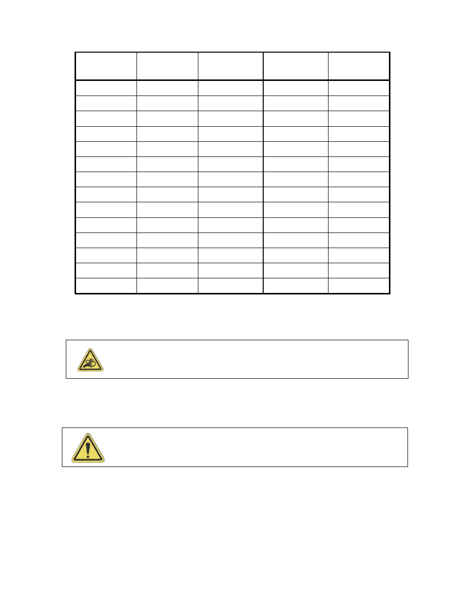
Table 2 - Guide Strip Sections required for a given diameter
Pipe Diameter
In / mm
Head
Section
05-0510-013B
Tail
Section
05-0510-013D
Short Center
Section
05-0510-013C
Long Center
Section
05-0510-013A
18 / 458
1
1
****
****
20 / 508
1
1
****
****
24 / 610
1
1
****
****
28 / 711
1
1
1
****
30 / 762
1
1
1
****
32 / 813
1
1
1
****
34 / 864
1
1
****
1
36 / 914
1
1
****
1
42 / 1067
1
1
2
****
48 / 1219
1
1
1
1
52 / 1321
1
1
****
2
54 / 1372
1
1
2
1
58 / 1473
1
1
2
1
60 / 1524
1
1
1
2
4.4.10 Place the end of the latch adjustment bars (Figure 1 Item F) of the latch handle assemblies into the
curved portion of the latch ends (Figure 1 Item A).
4.4.11 Adjust the end of the latch adjustment bars (Figure 1 Item F) until the handle of latch handle
assembly will lock in position.
4.4.1 Place the Maxi Jolli Chain Machine chain machine over the guide strip so the wheel are located on the
outside of the guide strip.
4.3.3
Place the Chain (Figure 5 Item 21) over the sprocket (Figure 5 Item 4A).
4.4.4
Lay the chain (Figure 5 Item 21) to rest on the sprocket (Figure 3 5 Item 4A).
4.4.14 When placing the chain around the pipe, place the chain (Figure 3 Item N21) between the dome nuts
located in the center of the guide strip.
4.4.15 Join the Chain Segments with Chain Junction Link (Figure 5 Item 21D) or Joint Bolt (Figure 5 Item
21A) and Nut (Figure 5 Item 21B). If one pin is removed the chain, the ends are joined using a Joint
Bolt (Figure 5 Item 21B) and Nut (Figure 5 Item 21A). If two pins are removed the chain is joined
with the Chain Junction Link (Figure 5 Item 21D)
4.4.16 To apply tension to the chain rotate both handles (Figure 5 Item 8E) over center.
WARNING: There is a potential crush hazard, if the hand and fingers are caught
between the edge of the guide strip and the pipe, when closing the guide strip
latches.
WARNING: When placing the chain (Figure 5 Item 21) on the sprocket (Figure 3 5
Item 4A) the hand can be pinched by the chain.