Mathey Dearman Maxi Jolli Chain Machine User Manual
Page 8
7
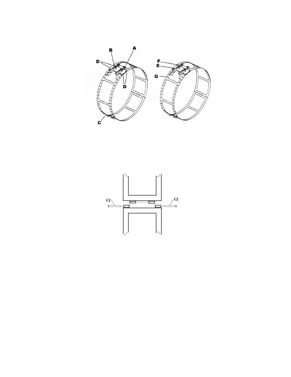
FIGURE 1
4.4.2 Form all sections of the guide strip so that they fit the pipe diameter to be cut as close as possible.
The better the sections of the guide strip fit the diameter of the pipe; the easier it will be to adjust and
latch the ends of the guide strip together.
FIGURE 2
4.4.3
Attach the sections of the guide strips together as shown in Figure 2 and insert the pins (C2).
4.4.4 The section containing the latch handle assemblies (B) should be at one end of the fully assembled
guide strip and the section containing the receiver section ends (A) should be at the other end.
4.4.5 It may be necessary to move the latch handle assembly along the holes in the latch section in order to
latch the guide strips to fit tightly around the pipe circumference. To move the latch Handle
assembly to the proper location, remove the counter screws and domed nuts (Figure 1 Item D) from
the latch handle assembly (Figure 1 Item B).
4.4.6
Place the latch handle assembly (Figure 1 Item B) base over the guide strip from which it was
removed.
4.4.7 Locate the nearest holes (Figure 1 Item G) in that section of the guide strip and mark them.
4.4.8 Place the latch handle assemblies (Figure 1 Item B) over the marked holes and insert countersunk
screws and nuts (Figure 1 Item D) in the latch handle assembly.
4.4.9
Tighten the domed nuts on the screws.