Rear panel – Marantz AV8801 User Manual
Page 168
165
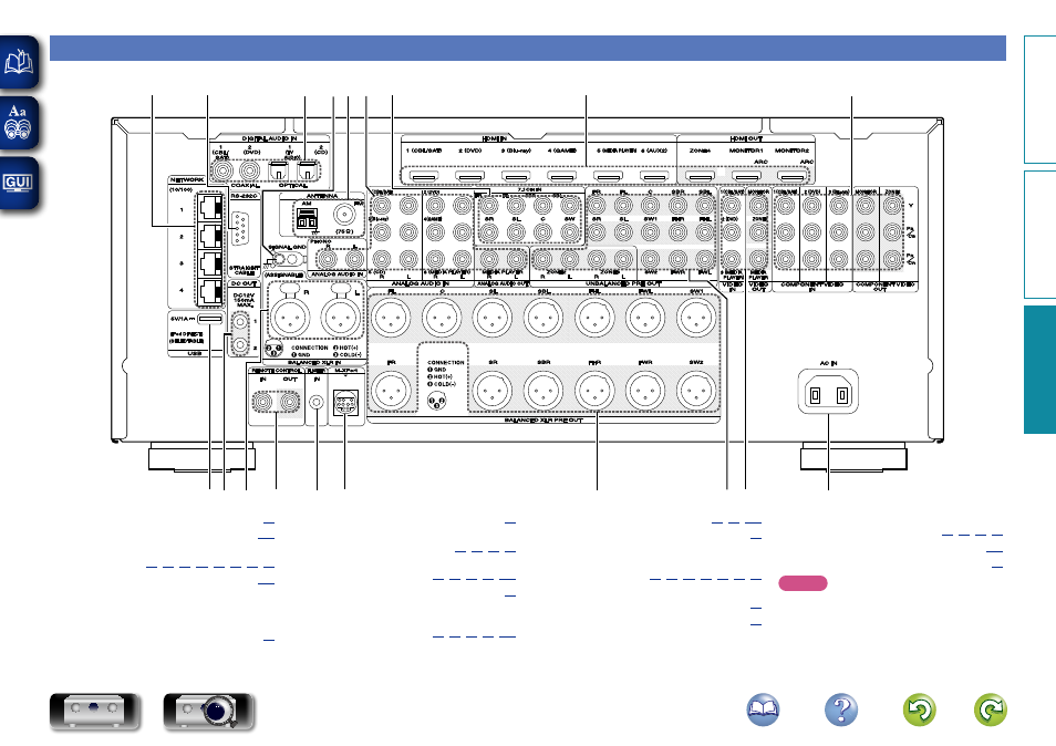
Rear panel
See the page indicated in parentheses ( ).
q w e
r
t
y
u
i o
Q0
Q1
Q2
Q3
Q4
Q5
Q6
Q7
Q8
Q9
q
USB port ······················································ (
w
DC OUT jacks ············································ (
e
BALANCED XLR IN terminals
··························· (
r
REMOTE CONTROL jacks ························ (
t
FLASHER IN jack
Used when using a control BOX or other such
control devices to control this unit.
y
M-XPort connector ····································· (
u
BALANCED XLR PRE OUT terminals ········ (
)
i
UNBALANCED RCA PRE OUT terminals
··················································· (
)
o
Video connectors
(VIDEO) ······························ (
)
Q0
AC inlet (AC IN) ··········································· (
)
Q1
Component video connectors
(COMPONENT VIDEO)
··········································· (
)
Q2
HDMI connectors ·························· (
Q3
7.1ch input connectors (7.1CH IN) ············ (
Q4
Analog audio connectors
(ANALOG AUDIO)
································· (
Q5
FM/AM antenna terminals
(ANTENNA) ················································· (
Q6
SIGNAL GND terminal ······························· (
Q7
Digital audio connectors
(DIGITAL AUDIO IN) ················· (
)
Q8
RS-232C connector ··································· (
)
Q9
Network connectors (NETWORK) ············· (
)
NOTE
Do not touch the inner pins of the connectors on
the rear panel. Electrostatic discharge may cause
permanent damage to the unit.
Basic v
ersion
A
dv
anced v
ersion
Inf
or
mations
Inf
or
mations
DVD