Electrical characteristics curves – Delta Electronics Series H48SA User Manual
Page 6
DS_H48SA12025_05052008
ELECTRICAL CHARACTERISTICS CURVES
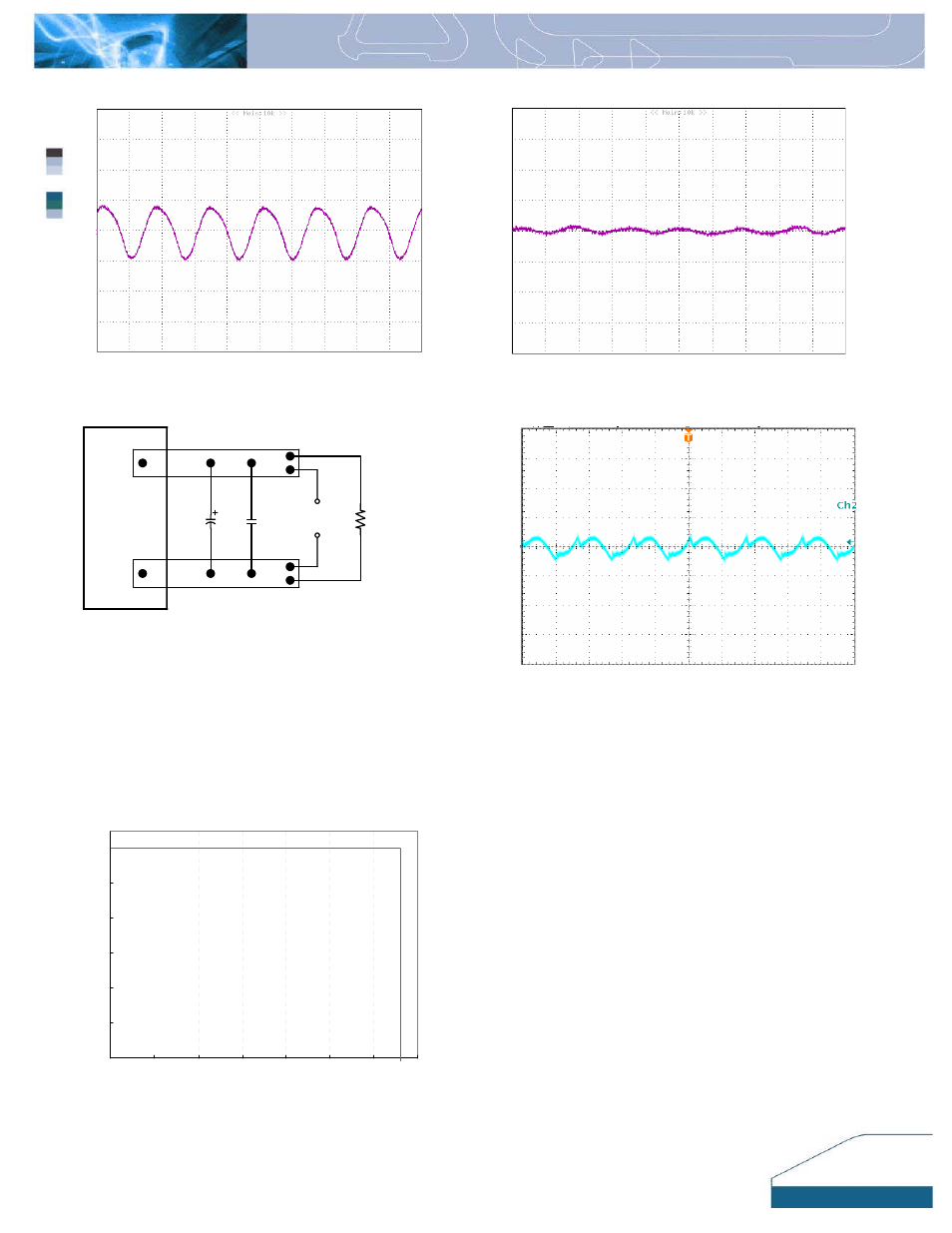
Figure 13:
Input Terminal Ripple Current, i
c
, at nominal input
voltage and rated load current with 12µH source impedance
and 100µF electrolytic capacitor, 500 mA/div, 2us/div.
Figure
14:
Input reflected ripple current, i
s
, through a 12µH
source inductor at nominal input voltage and rated load current,
20 mA/div, 2us/div.
Vo(-)
Vo(+)
10u
1u
Copper Strip
SCOPE
RESISTIVE
LOAD
Figure 15:
Output voltage noise and ripple measurement
test setup
Figure
16:
Output voltage ripple at nominal input voltage and
rated load current, 50mV/div, 2us/div. Load capacitance: 1µF
ceramic capacitor and 10µF tantalum capacitor. Bandwidth: 20
MHz. Scope measurement should be made using a BNC cable
(length shorter than 20 inches). Position the load between 51
mm to 76 mm (2 inches to 3 inches) from the module.
0
2
4
6
8
10
12
0
5
10
15
20
25
30
35
Output Current (A)
O
u
tput
V
o
ltage (
V
)
Figure 17:
Output voltage vs. load current showing typical
current limit curves and converter shutdown points.
6
0
0
0