Dimplex DF3215 User Manual
Page 9
NOTE
When the Low Battery icon is present on the remote control it is recommended to replace
the batteries promptly, to maintain full functionality of the remote/fireplace (FIGURE 5).
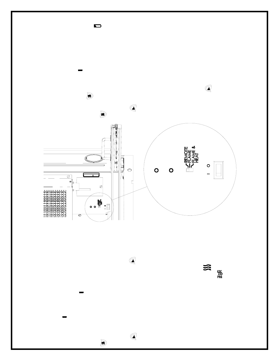
INITIALIZING THE REMOTE CONTROL
1. Plug cord into 120 volt wall outlet.
2. Turn ON the electrical power at the circuit breaker.
3. Ensure the Main On/Off switch located inside the fireplace in the upper right hand
corner is in the ON position.
4. Set the 3 position manual control to the Remote position (left position).
5. Press and hold the initialization button on the unit.
6. While holding the initialization button, press the flame/heat ON/OFF button or the
Purifire™ ON/OFF button on the remote control transmitter.
7. Release the initialization button on the unit.
8. Press the Flame/Heat On/Off button to turn the Flame/Heat function ON or press the
Purifire™ On/Off button to turn the Purifire™ function ON.
FREQUENCY INTERFERENCE
If the fireplace does not respond properly to the remote control, the remote operating
frequency may have to be reset. The remote control can send another frequency code to the
circuit board to eliminate interference.
1. Press the Flame/Heat On/Off button to turn the Flame/Heat ON.
2. Press the ENTER button on the remote control, the middle display flashes.
3. Use the direction buttons on the hand held remote to move the cursor to and press
ENTER.
4. Press and hold the initialization button on the unit.
5. Press and hold left direction button on the remote control.
6. A descending bar graph will appear on the screen.
7. The green indicator light will flash on the unit when the new frequency code has been
stored.
8. Release left direction button on the remote control.
9. Release the initialization button on the unit.
10. Press ENTER to return to the main menu.
11. Press the Flame/Heat On/Off button to turn the Flame/Heat function ON or press the
Purifire™ On/Off button to turn the Purifire™ function ON.
Indicator
Light
Initialization
Button
3 Position
Manual
Control
FIGURE 4
Main
On/Off
Switch
7
SERIAL No.
XXX
XX