Operating controls and adjustments, Fastening stand to supporting surface, Starting and stopping saw – Delta 36-600 User Manual
Page 16: Locking switch in the “off” position, Overload protection, Blade raising mechanism, Blade tilting mechanism
16
FASTENING STAND TO SUPPORTING SURFACE
IF DURING OPERATION THERE IS ANY TENDENCY FOR THE TOOL TO TIP OVER, SLIDE OR WALK ON THE
SUPPORTING SURFACE, REMOVE THE RUBBER FEET FROM THE STAND AND SECURE THE STAND TO THE
FLOOR.
OPERATING CONTROLS AND ADJUSTMENTS
STARTING AND
STOPPING SAW
The switch (A) is located on the front panel of the saw
cabinet, as shown in Fig. 33. To turn the saw “ON” move
the switch to the up position. To turn the saw “OFF”
move the switch (A) to the down position.
LOCKING SWITCH IN
THE “OFF” POSITION
IMPORTANT: When the tool is not in use, the switch
should be locked in the “OFF” position to prevent
unauthorized use. Grasp the switch toggle (B) and pull
it out as shown in Fig. 34. With the switch toggle (B)
removed the switch will not operate. However, should
the switch toggle be removed while the saw is running, it
can be turned “OFF” once, but cannot be restarted
without inserting the switch toggle (B).
OVERLOAD PROTECTION
Your saw is equipped with a reset overload relay button
(C) Fig. 34. If the motor shuts off or fails to start due to
over-loading (cutting stock too fast, using a dull blade,
using the saw beyond its capacity, etc.) or low voltage,
turn the switch to the “OFF” position, let the motor cool
three to five minutes and push the reset button (C), which
will reset the overload device. The motor can then be
turned on again in the usual manner.
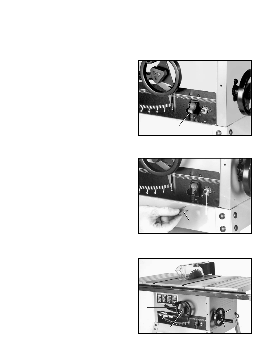
BLADE RAISING MECHANISM
To raise or lower the saw blade, loosen lock knob (A) and
turn the blade raising handwheel (B) Fig. 35. When the
desired blade height is obtained, tighten lock knob (A).
BLADE TILTING MECHANISM
To tilt the saw blade for bevel cutting, loosen lock knob
(C) and turn the tilting handwheel (D) Fig. 35. When the
desired blade angle is obtained, tighten lock knob (C).
Fig. 33
Fig. 34
Fig. 35
A
C
B
B
A
D
C