Part 4. installing a jumper splice – Infloor Heating Cable Repair Kit User Manual
Page 3
and flows into the wires, continue
heating for another 3 seconds. If
the heat is removed too soon, an
incomplete solder connection will
result, causing connection failure
later. When the solder is completely
melted, begin moving the heat gun
back and forth under the rest of the
solder tube to shrink the tube and
cause the adhesive bands at the ends
to melt and flow onto the wire insu-
lation. After the tube is completely
shrunk and the adhesive bands are
fully melted, stop heating the tube.
Additional heating will not help and
may cause either scorching of the
tube or splice failure. Allow the sol-
der tube to cool for about 1 minute.
Step 3.15. REPEAT Steps 3.12
through 3.14 for the other heating
wire.
Step 3.16. Slide a ground solder
tube over a ground braid lead.
Overlap the braid ends and twist
them to help hold them together.
Slide the ground solder tube over the
twisted braid ends, centering them
under the ring of solder.
Step 3.17. Heat the tube to shrink
it completely and cause the solder
to flow into the twisted wires com-
pletely. When it cools, the connection
should be secure.
Step 3.18. The connection should
now be complete and ready to test.
Go to Step 5.1 under “Testing the
Repair.”
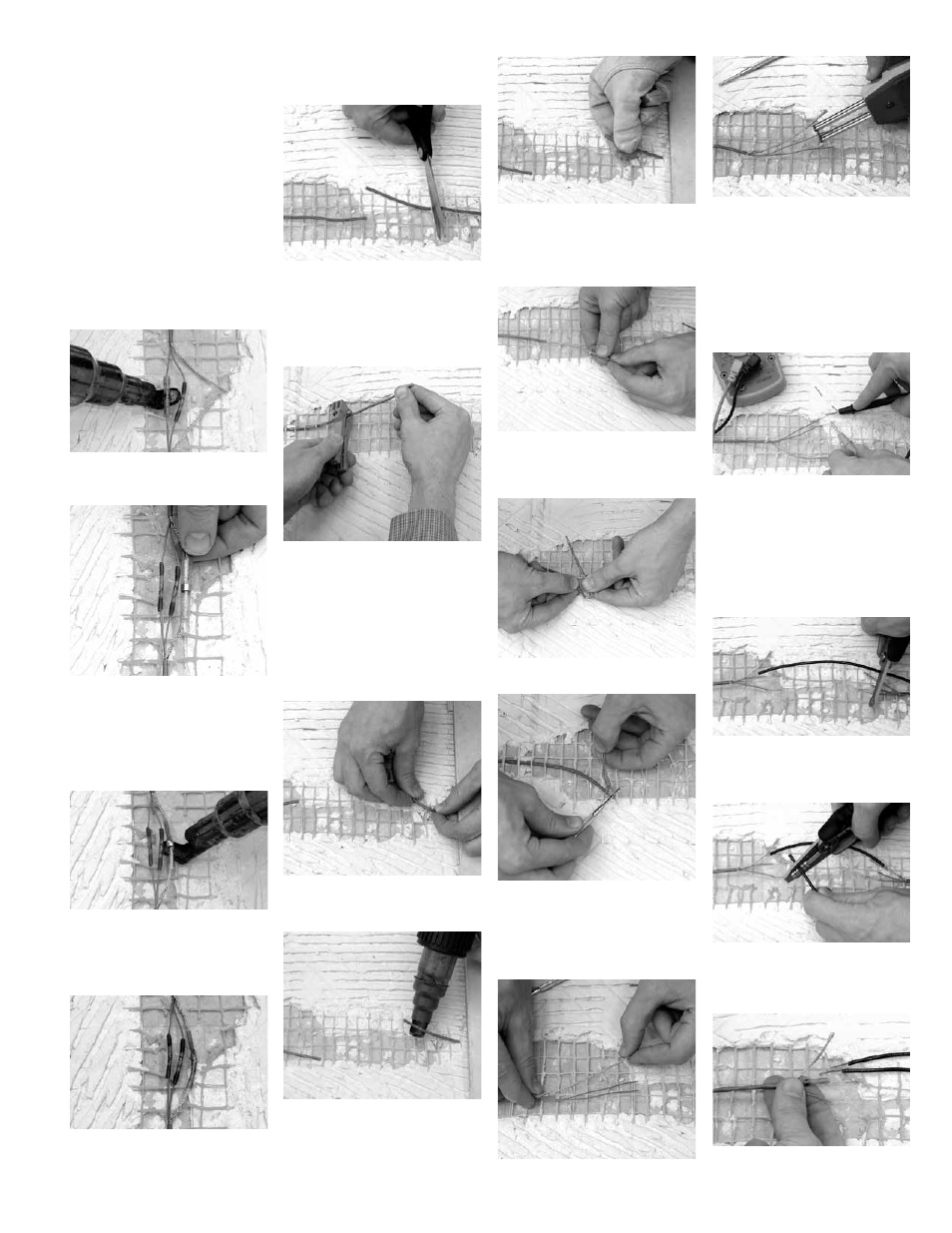
Step 4.1. Cut out a 2”- to 3”-long
section of the heating cable around
the damaged area, creating two ends
or leads.
If the cable is not a jacketed heating
cable, SKIP to Step 4.6.
Step 4.2. Use the scoring tool to
carefully score the jacket about 2”
from the end of each lead. Do this
by placing the cable lead into the
V-notch of the tool and rotating the
tool only one or two revolutions
around the cable. Do not place any
additional pressure on the tool head
to cut deeper. Let the tool apply its
own spring-loaded pressure.
Part 4. Installing a
Jumper Splice
Step 4.3. Bend the cable to snap the
jacket slug completely loose at the
score.
Step 4.4. Use the heat gun (set to HI
temperature, about 1000°F) and move
the gun back and forth under the
jacket slug for about 3 to 4 seconds
until it starts to loosen and slightly
shrinks at the ends.
Step 4.5. Use a glove or other pro-
tective cloth to pull off the loosened
jacket slug. Do not touch the hot
jacket slug with bare fingers. The slug
will be very hot and will burn!
Step 4.6. Loosen the braid by push-
ing back on the braid about 1/4”, caus-
ing the ends of the heating wires to
be exposed.
Step 4.7. Bend the cable back onto
itself.
Step 4.8. Use the small screwdriver,
paper clip, fingernail, or similar instru-
ment to pry between the braid and
make an opening through which to
pull the heating wires. Pull each wire
through the braid.
Step 4.9. Pull the braid tight to make
it into a pigtail.
Step 4.10. Use the thermal wire
strippers to carefully strip off exactly
1/2” of the insulation from the heat-
ing wires. Count the little heating
elements to make sure none were
cut off and thereby cause a hot spot
or possible failure. A fiber strand will
also be found among the heating ele-
ments. There is no need to separate
or remove this fiber strand.
Step 4.11. Use the digital multi-meter
and TDR at this repair location before
proceeding. Check for any additional
damage locations in the heating
cable by “looking” in both directions.
For assistance in using these instru-
ments, consult the instructions that
came with them or contact Infloor
Sales & Service SW.
Step 4.12. Cut the black jumper
wires shorter, if necessary, so that
they overlap the stripped ends of the
heating wires.
Step 4.13. Use the 16 AWG setting
on the wire strippers to strip off
exactly 1/2” of the insulation from
both ends of the black jumper wires.
Step 4.14. Slide a solder tube over
one of the heating wires on one lead
of the heating cable.
Heating Cable Repair Kit Guidelines
3