Txlp/2r cable, Thermostat and controls – Infloor Heavy-Duty Cable User Manual
Page 4
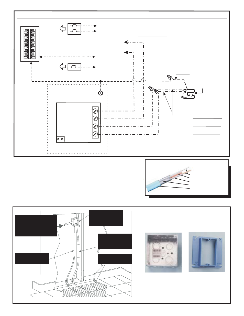
Electrical Installation Diagram
Junction Box
Metal Double Gang
Junction Box
Cover
Carlon Blue Single
All Components
Readily Available
at Electronic &
Home Super Stores.
Thermostat and Controls:
Always install the thermostat per
local code. When using the floor sensing thermostat, it is important to
make sure that the floor sensor is placed 1-3’ out into the heated floor
and centered between two cable runs (See Diagram below). Where
cable system amp load is greater than 16, an RFWCK Control Box is
available.
FW.INST.Ver.1.0209R
Conduit to GFIC or
standard breaker
power source as
required
½”Conduit for floor
sensor only
Double Gang
Metal Box
Electrical conduit
sized per code
Heating cable
TXLP/2R
Cable
High Quality Conductor
Stranded Ground Wire
XLPE Insulation
Waterproof Metallic Shield
PVC Covering
CABLE AMPERAGE
DRAW MUST NOT
EXCEED 16 AMPS
CABLE AMPERAGE
DRAW MUST NOT
EXCEED 16 AMPS
220,230 OR 240 VOLT
Circuit Breaker
220,230 OR 240 VOLT
Circuit Breaker
Metal, double gang
wall box
Ground
Box must be grounded.
To Floor Sensor
(Polarity is not important)
Heating cable
TXLP/2R
Uninsulated,
“cold end” ground lead
SENSOR
NEUTRAL IF 120 VOLT
HOT L1
LOAD HOT
LINE
LOAD 16 AMP MAX
OR HOT IF 230 VOLT
LOAD NEUTRAL IF 120VOLT
/ OR LOAD HOT IF 230 VOLT
Circuit Breaker Panel
Circuit Breaker Panel
THE POWER LEAD
FOR THE THERMOSTAT
(If the cable is 220, 230 or 240 volt)
THE POWER LEAD
FOR THE THERMOSTAT
(If the cable is 220, 230 or 240 volt)
POWER LEADS FOR
THE THERMOSTAT
POWER LEADS FOR
THE THERMOSTAT
120 Volt
Circuit Breaker
120 Volt
Circuit Breaker
In Panel
In Panel
In Panel
In Panel
White wire
White wire
Black wire
Black wire
Bare copper wire
Bare copper wire
Black wire
Black wire
red wire
red wire
Caution: Supply the TXLP/2R Heating cable
with the voltage it was tagged with at the factory
NEVER EVER CUT THE HEATING CABLE
Caution: Supply the TXLP/2R Heating cable
with the voltage it was tagged with at the factory
NEVER EVER CUT THE HEATING CABLE
Clear
Insulated Wires
Clear
Insulated Wires
Cold lead
Bulb
Cold lead
Bulb
If cable voltage is 120 volts use the bottom
left circuit breaker diagram. If the cable
voltage is 220, 230 or 240 volts use
the top left circuit breaker wiring diagram
If cable voltage is 120 volts use the bottom
left circuit breaker diagram. If the cable
voltage is 220, 230 or 240 volts use
the top left circuit breaker wiring diagram
L2 OR N
UCCG THERMOSTAT WIRING DIAGRAM
UCCG THERMOSTAT WIRING DIAGRAM
THERMOSTAT
120/240 LINE VOLTAGE, 16 AMP MAX. LOAD
120/240 LINE VOLTAGE, 16 AMP MAX. LOAD
TO THE NEUTRAL BUSS IN THE CIRCUIT BREAKER PANEL
TO THE NEUTRAL BUSS IN THE CIRCUIT BREAKER PANEL
THE POWER LEAD
FOR THE THERMOSTAT
To Floor Sensor
(Polarity is not important.)
(If the voltage of the cable is 120)
IMPORTANT:
DO NOT MIX VOLTAGES
The supply
voltage used for the
heating cable should be
the same voltage used
for the thermostat.
SUGGESTED WIRING TO BE PERFORMED BY LICENSED ELECTRICIAN IN ACCORDANCE WITH ALL APPLICABLE LOCAL, STATE, & FEDERAL REQUIREMENTS.