Powermax – Hypertherm Powermax65 Service Manual Rev.1 User Manual
Page 137
TroubleshooTing and sysTem TesTs
powermax
65/85
Service Manual
5-11
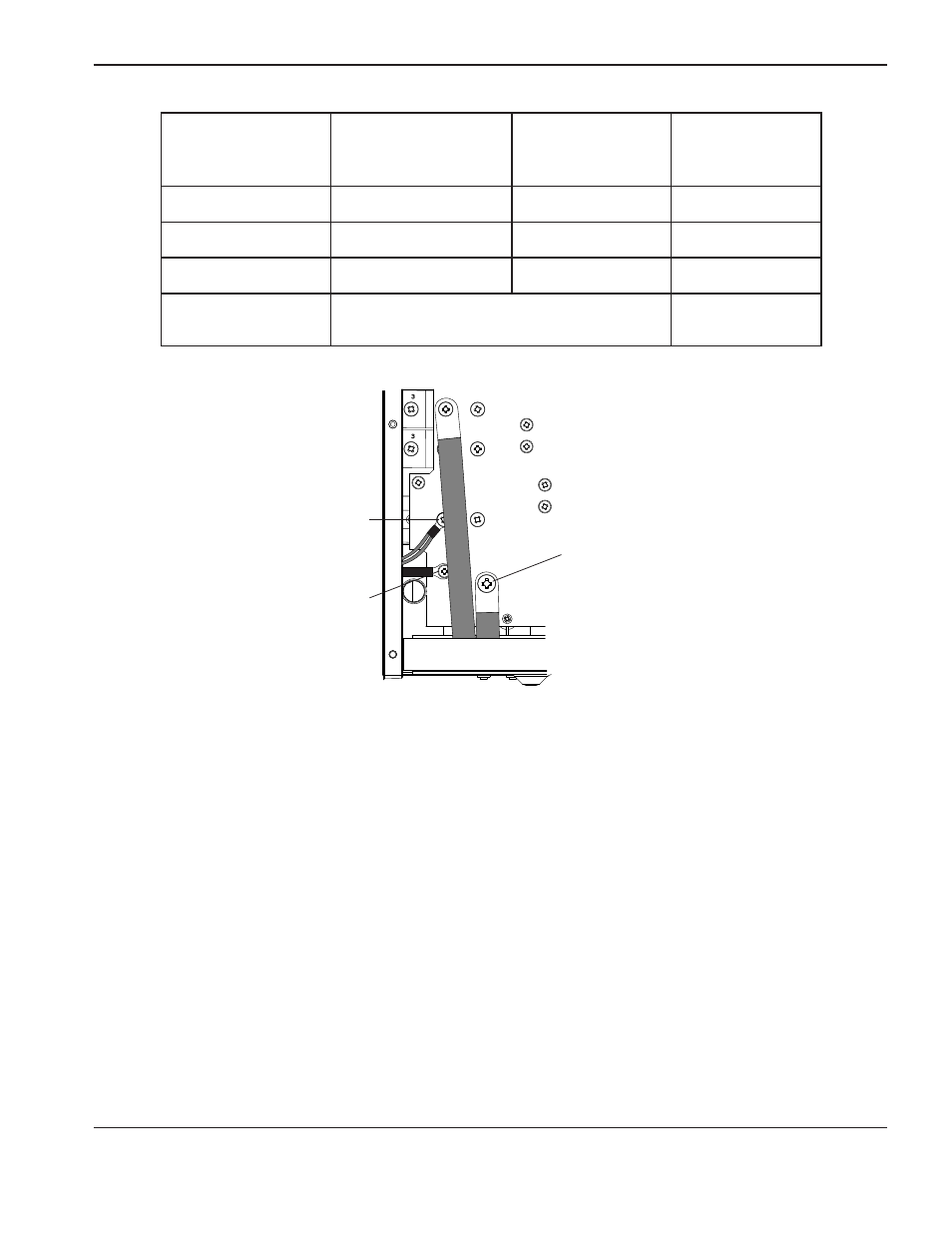
Measure resistance
from
200 – 600 V CSA power
board location
400 V CE power
board location
Approximate
values
Work lead to nozzle
J26 to black wire
J27 to black wire
230 kΩ
Work lead to electrode
J26 to red wire
J27 to red wire
15 kΩ
Electrode to nozzle
red wire to black wire
red wire to black wire
230 kΩ
Output to ground
> 20 MΩ
If no problems were found during the visual inspection or the initial resistance check, and the power supply still does not
operate correctly, see the Troubleshooting guide.
Note: The Troubleshooting guide provides most probable causes and solutions. Study the system wiring diagram
and understand the theory of operation before troubleshooting. Before purchasing any major replacement
component, verify the problem with Hypertherm Technical Service or the nearest Hypertherm repair facility.
Black wire
Red wire
J28 CSA
J29 CE
J26 CSA
J27 CE
WORK
LEAD