Hoefer VP200 User Manual
Page 26
•
p18
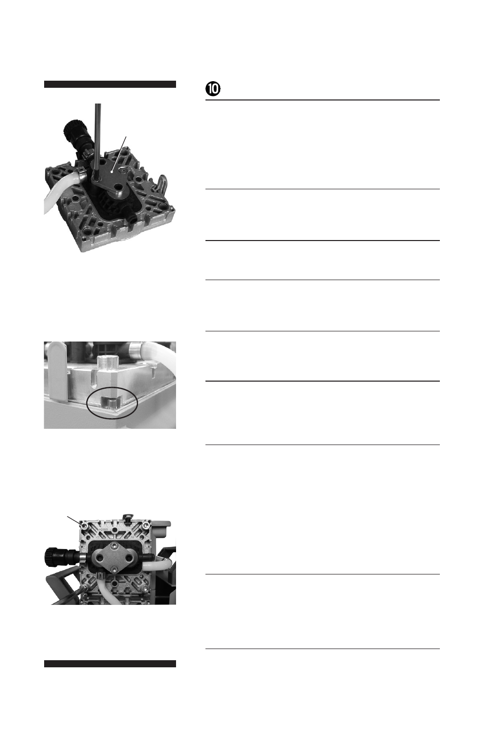
Valve head with gas ballast or hose nozzle connection:
Insert square nut (K, not shown) in the groove of the
head cover (J) or position square nut in the groove
and then screw on connection fastener. Loosely fasten
fillister head screw (L, not shown).
!
Position clamping bracket (S) with countersunk bores
facing upwards.
@
Align the countersunk bores with the threaded pegs.
#
Loosely fasten the countersunk screws and correct the
alignment of the valve heads if necessary.
$
Tighten countersunk screws with Torx screwdriver T20.
Torque: 2.2 ft lb
f
(3 Nm).
%
Bring the diaphragms (F) into a position, in which
they are in contact with the housing (C) and centered
with respect to the bore.
^
Put on head cover (J) with valve heads (O) and
connections attached.
Pay attention to the correct orientation of the head
covers: Housing with head alignment pin: The head
alignment pin (A, not shown) at the pump housing (C)
has to fit into the recess at the head cover (J).
Housing with mark (A, not shown). Align the recess at
the head cover with the mark at the pump housing.
&
Loosely screw in the Allen head screws (H) at the
head covers diagonally at first slightly with a 5 mm
wide Allen key, then tighten. Recommended torque:
8.9 ft lb
f
(12 Nm).
*
Slide the caps (I) into the head cover.
Step 11
Step 15
Step 17
S
H