Hoefer VP200 User Manual
Page 25
•
p17
4
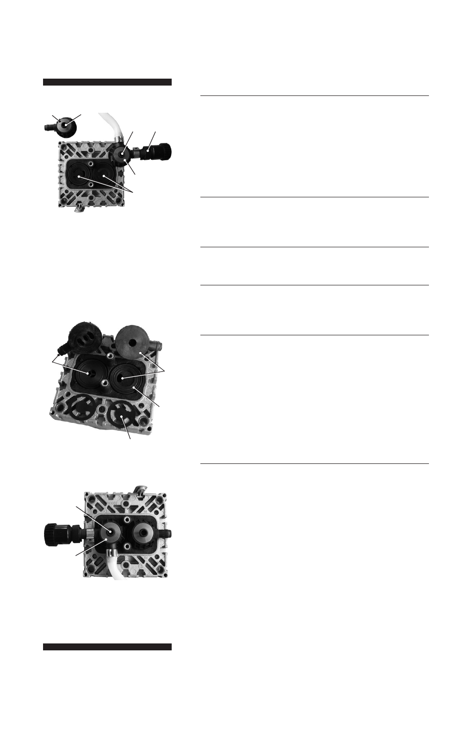
Remove valve heads (O) along with the disc springs
(R), connection tube if applicable, hose nozzles (P)
and connection fasteners (Q) or move the valve heads
carefully aside. Note position and orientation of the
valve heads.
Note position and alignment of valves (N).
5
Check valves (N) and O-rings (M) for damage
and soiling.
6
Replace valves or O-rings if necessary.
7
Use petroleum ether or other industrial solvent to
remove deposits. Do not inhale vapors.
8
Insert O-rings (M) and valves (N). See figure for the
correct position of the valves:
Inlet side (IN): Marked “IN” next to the valve seat.
The valve tongue points at the kidney-shaped orifice
in the valve seat.
Outlet side (EX): Marked with “EX” next to the valve
seat. The valve is oriented the same direction as the
valve at the inlet side.
9
Position valve heads (O), with hose nozzle (P), if
applicable, connection tube or connection fastener
(Q), and disc springs (R) on the valve seats. Position
disc springs with large opening downwards. Pay atten-
tion to the correct orientation of the valve heads.
Center the valve head with respect to the valve seat.
The valve head must lie flat on the valve seat.
Step 4
Step 8
Step 9
O
Q
R
R
N
O
N
M
IN
EX
O
R