Herrtronic, Model 6000 – Herrmidifier Herrtronic 6000 Series User Manual
Page 10
Herrtronic
®
Model 6000
I n s t a l l a t i o n , O p e r a t i o n , & M a i n t e n a n c e M a n u a l
10
www.herrmidifier-hvac.com
SECTION IV OPERATING INSTRUCTIONS
Start-up Instructions
1. Check that the humidifier is properly mounted and level.
2. Check that the water fill and drain are properly connected.
3. Check that the correct voltage and amperage service are
supplied.
4. Check all controls are wired properly.
5. Check that the steam distributor is properly installed and
that the steam hose has been properly routed without any
kinks or flat spots.
6. With power off, double check all electrical connections and
plumbing connections to insure that they did not loosen dur-
ing shipment.
7. With the “on-off-drain” switch in the “off” position, and the
control and high limit (ducted versions only) humidistats
at their lowest settings, turn on the main disconnect. The
contactor should remain deenergized and the power light
should remain “off”. Place the “on-off-drain” switch in the
“on” position and the power light should illuminate.
8. Turn the control and high limit (ducted versions only) hu-
midistats up to their highest setting. The contactor should
pull in.
9. After approximately a 5 second delay, the fill valve ener-
gizes and water begins to fill the cylinder to the preset amp
level or cylinder full condition, depending on the incoming
water supply. When starting up the unit, it is best to put an
amp clamp on the power leg that passes through the
NOTE:
If upon initial start-up of this humidifier the cylinder is
slow in heating and/or the service light continues to come
on, drain the tank to 1/4 full. Turn off power at breaker, ob-
tain some Alka-Seltzer tablets and crumble 1/2 of one tab-
let (Alka-Seltzer) into the grey fill tee. Change the middle
blue dial on the left side of the circuit board, R18, from
90% to 87%. Then turn the breaker on and run the unit. If
you have had to use these this step on a 240V unit (6000-
2,4), it is advisable that you order a GT-176-1 replacement
cylinder rather than the standard replacement cylinder in
the future so this procedure will not need to be repeated.
Upon receipt of the GT-176-1 cylinder, adjust the dial,
R18, on the circuit board back to 90%.
toroid transformer. Insure that the humidifier fills to “cylinder
full” (approximately 1.5” from the top of the cylinder), or that
the amperage reaches the data plate maximum and the fill
valve de-energizes.
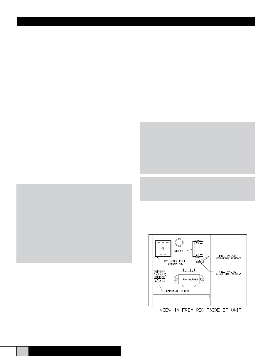
10. All units are equipped with a drain tempering feature which
mixes cold fill water with the hot drain water to protect drain
piping. Depending on your fill water pressure, some adjust-
ment of the fill metering valve may be necessary to insure
drain water of less than 140°F (See Figure 9). To deacti-
vate, remove diode from socket CRI8 from circuit board
(See Figure 12).
11. Reset control and high limit humidistats to their desired set-
tings. Typical control humidistat settings are 30-40% and
the high limit humidistat settings are 65-70%.
NOTE:
The capacity of the humidifier can be adjusted between
50% and 100% of the maximum level by adjusting the
capacity adjustment potentiometer (labeled R39) on the
main circuit board. All blower versions are set from the
factory to produce 4 lbs/hr. If the psychrometric condi-
tions permit, the 6000—2 may be increased to 8 lbs/hr
by adjusting R39 from 50% to 100% capacity. Refer to
figure 12.
CAUTION!
Inadequate airflow may allow humidity to collect in areas
causing condensation.
Figure 9
VIEW IN FROM RIGHTSIDE OF UNIT
TRANSFORMER
L1 L2
RELAY
TERMINAL BLOCK
FILL VALVE
MOUNTING SCREWS
FILL VALVE
ADJUSTING SCREW
CYLINDER FULL
INTERFACE