Operation – Gullco GP-250 User Manual
Page 6
4
OPERATION
Note: The electrical and mechanical installation of the AutoCycle positioner is explained in the
Technical Manual.
Through the use of the optical tachometer closed loop feedback circuitry, the motor control can
obtain constant speed control of the AutoCycle welding positioner, as well as determine the amount
of rotational distance travelled. The motor and the control operate on 24 VDC, supplied by a power
supply located in the base of the positioner tower. Therefore, all operator interface devices (except
the power on/off switch) are subjected to signal level voltages only.
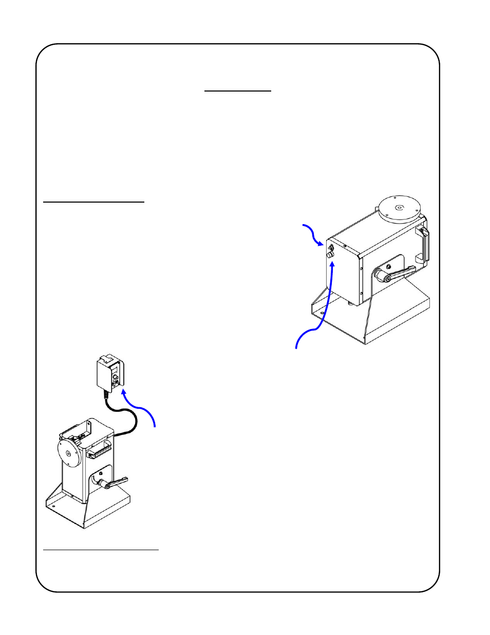
Local Control Devices
The power On/Off switch is located at the bottom of the positioner
tower and is used to disconnect the power to the rest of the
control circuitry.
I = On, O = Off.
WARNING!
The motor control must not be continually started
and stopped by the removal and reapplying of
power to the control. Turning the power off to the
control will not provide instant braking and
continued use will damage the control. Allow ten
(10) seconds after the removal of power before
reapplying the power to the motor control.
The fuse holder is located at the bottom of the positioner tower and
allows accessibility to the main AC fuse by pushing the cap in towards
the main body and twisting in a counter-clockwise direction.
The AutoCycle welding positioner typically
*
uses a Gullco GSP-2010-2
microprocessor based motor control, located in a remote pendant
attached to the positioner by 6ft [1.8 Mtrs] of control cable.
*
If requested at time of purchase, a different style of GSP control can be substituted, where the Program
Variable Selector Switch is located under a hole plug in the face plate (reducing the possibility of
unwanted changes to the AutoCycle routine once set).