Gullco GP-250 User Manual
Page 13
11
To make changes to the program variables, turn the power on and place the Run/Stop switch in the
Stop position, then rotate the Program Variable Selector switch to the variable (parameter) to be
altered (the Auto Cycle Mode L.E.D. will flash on and off). The number of the variable parameter
will be displayed when the Forward/Neutral/Reverse switch is in the Neutral position. I.e. “P. 1”, “P.
2”, “P. 3”, etc. To see the current value/setting of the variable, place the Forward/Neutral/Reverse
switch in either the Forward or Reverse position. To increment the value/setting, place the
Forward/Neutral/Reverse switch in the Forward position and press the Cycle Push Button. To
decrement the value/setting, place the Forward/Neutral/Reverse switch in the Reverse position and
press the Cycle Push Button. Pressing the Cycle Push Button briefly will increment/decrement the
value/setting by one, whereas keeping the Cycle Push Button depressed will scroll through the
values/settings until released. The speed display and/or the individual L.E.D.’s will indicate the
chosen value/setting. When all of the program variables are set, place the Program Variable
Selector switch back to the zero position (the Auto Cycle Mode L.E.D. will stop flashing).
The values/settings of the variables are stored on the product/application specific micro-processor
chip. If the chip is replaced, the
values/settings of the variables will
need to be re-entered.
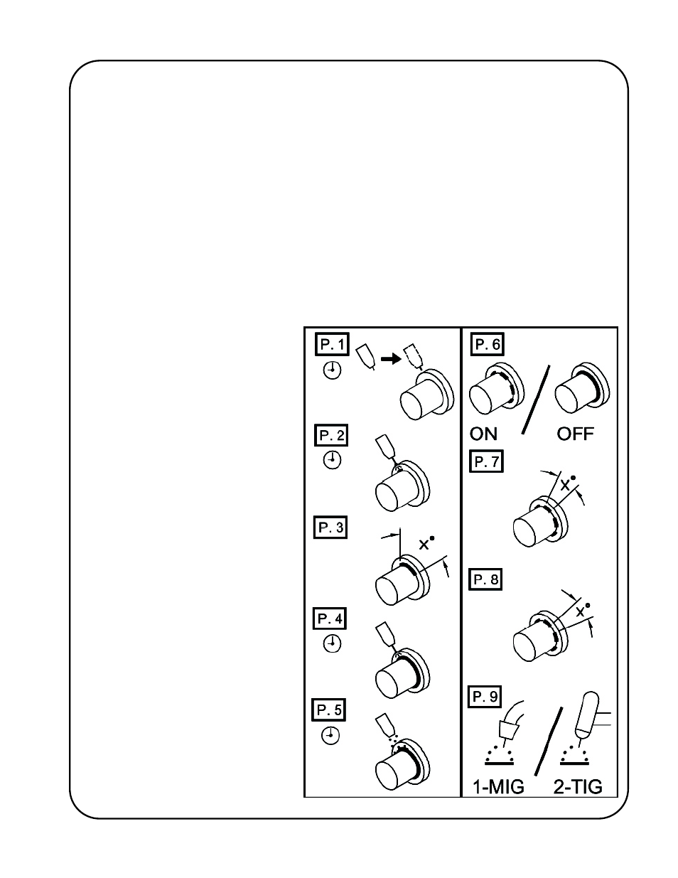
The adjacent label is applied to each
AutoCycle weld positioner to
graphically identify the individual
programmable parameters/variables: