Gullco GP-250 User Manual
Page 12
10
provides time for any pre-flow function as well as allowing the arc to establish prior to
commencing the weld motion.
2-10. Upon completion of the Rotation Start Delay (P. 2), the weld rotation will start to travel in
the forward direction at the speed set by the Speed Adjustment knob.
2-11. The cycle will continue as described between section 2-5 and section 2-10 until the total
angular rotation reaches the value set by the programmable Degrees Of Rotation
parameter (P. 3), at which point the cycle will closedown as described in section 2-12.
2-12. Regardless of whether the automatic cycle is performing a continuous weld or a stitch
weld routine, when the angular rotation reaches the same value as the programmable
Degrees Of Rotation parameter (P. 3), the optional arc signal relay will de-energize and
the programmable Crater-Fill/Slope-Out Delay (P. 4) timing cycle will commence. When
the programmable Weld Cessation variable (P. 9) is set to “2”, the Crater-Fill/Slope-Out
Delay is used to keep the turntable rotating for a programmable duration, after the arc
signal has been de-activated, providing a slope-out function.
2-13. Upon completion of the Crater-Fill/Slope-Out Delay (P. 4), the rotation ceases and the
programmable Post Weld Delay (P. 5) timing cycle will commence. This allows time for
any burn-back and or post-flow functions, prior to the retraction of the optional pneumatic
gun positioning slide (where applicable).
2-14. Upon completion of the Post Weld Delay, the optional gun slide solenoid relay will be de-
energized and the automatic cycle will be complete. “End” will be displayed to indicate the
completion.
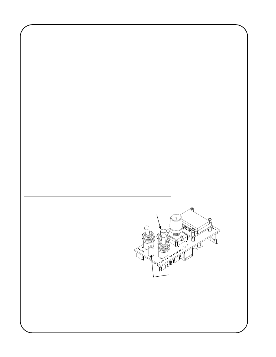
Programming The Automatic Cycle Parameters/Variables
The Program Variable Selector Switch is
used to select the different programmable
parameters that allow the operator to
change their values and settings and so
define how the automatic cycle will
function. The Program Variable Selector
Switch is located between and below the
Run/Stop switch and the
Forward/Neutral/Reverse switch of the
GSP control. The GSP control that is
typically supplied with the AutoCycle weld
positioner has a Program Variable Selector
Switch, which extend through the faceplate
of the control. Other styles of control are
available where the removal of a hole-plug for access and a small flat-bladed screwdriver for
adjustment are required (as shown in adjacent sketch).
Zero (0) (top dead center) is the normal operating location for the switch. When in any position
other than zero (0) the control is in programming mode, the round,
Preset Cycle L.E.D.
in the bottom
right hand corner of the display will flash and the motor control will not allow normal operation.
Cycle Push Button
Program Variable Selector Switch
Extended or Recessed (shown)