Shipping, inspection and storage, Installation – Groth 1400 User Manual
Page 5
4
SHIPPING, INSPECTION AND
STORAGE
The POV is packed and supported to prevent
damage or contamination during shipping. It
should be similarly protected during subsequent
handling and storage. Always keep all ports
plugged to prevent intrusion of foreign materials.
Inspect the valve for any sign of damage that
may have occurred in shipment and report this
to the carrier. If there are indications of physical
damage or internal contamination, the valve
must be disassembled, cleaned and inspected
before installation. The spring adjustment cap
and blowdown screw locknut will be "car sealed"
to ensure that the factory pressure setting has
not been altered.
Inspect the valve for any sign of damage that
may have occurred in shipment and report this
to the carrier and Groth Corporation.
Lifting eyes are provided on the upper actuator
for handling the valve. To avoid damage to the
lower flange surface, set the valve on a soft
clean gasket material until it is ready to be
installed. It should be stored in a clean
environment until it is to be mounted on the tank.
The pilot pickup fitting is in the body and must
be kept completely free of all foreign materials.
DO NOT store the valve directly on the ground.
INSTALLATION
The 1400 Series valves are precision devices
that must be handled carefully to ensure seat
tightness.
1. At installation, the valve should be smoothly
lifted into position using the lifting eyes on
the actuator. Use the actuator housing to
align the valve directly over the tank nozzle.
Do NOT use the pilot valve or pickup line to
pull the valve into position.
2. Aluminum valve bodies should be
connected with flat faced 150# ANSI
flanges. A full faced gasket is
recommended. Mating flanges should be
flat within .020" and clean, free of scratches,
corrosion and tool marks.
3. Each valve is leak tested at the factory as
part of our standard inspection procedures.
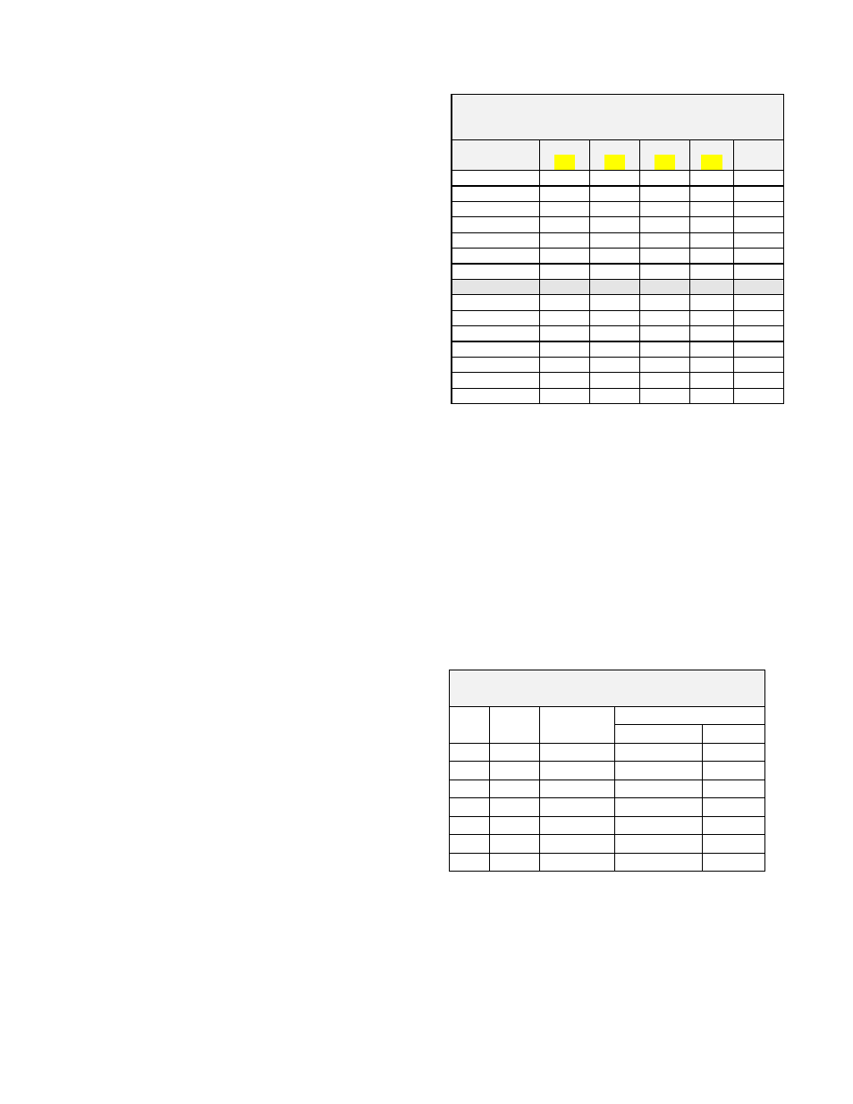
4. Inspect the gasket; make sure that the
material is suitable for the service. Gasket
dimensions are listed below, Table 2. Full
gaskets must be used with flat face flanges.
Either full or ring gaskets may be used with
raised face flanges.
Table 2
Body Flange Gasket Dimensions
150# ANSI
Flange*
O.D.
(IN)
I.D.
(IN)
B.C.
(IN)
Hole
(IN)
Qty
2” RF
4.12
2.38
---
---
---
3” RF
5.38
3.50
---
---
---
4" RF
6.88
4.50
---
---
---
6” RF
8.75
6.62
---
---
---
8” RF
11.00
8.62
---
---
---
10” RF
13.38
10.80
---
---
---
12” RF
16.12
12.80
---
---
---
2"
FF
6.00 2.00 4.75
0.75 4
3"
FF
7.50 3.00 6.00
0.75 4
4”
FF
9.00 4.00 7.50
0.75 8
6” FF
11.00
6.00
9.50
0.88
8
8” FF
13.50
8.00
11.75
0.88
8
10” FF
16.00
10.0
14.25
1.00
12
12” FF
19.00
12.0
17.00
1.00
12
* RF = Raised Face, FF = Flat Face
5. Lubricate all studs and nuts with an
appropriate thread lubricant. If stainless
steel fasteners are used, use an anti-seize
lubricant such as moly-disulfide (Table 6).
6. Center the gasket within the bolt circle of
the tank nozzle flange.
7. Set the valve carefully on the nozzle.
8. Install nuts and lock-washers and torque all
fasteners to half the recommended value in
a staggered, alternating pattern. Consult
with Plant and/or Maintenance Personnel
for appropriate practices and standards.
Table 3
Recommended Minimum Torque Values*
Size
Qty
Holes
Bolt
(UNC)
Torque (lb-ft)
Raised Face Flat Face
2”
4
5/ 8” - 11
31
81
3”
4
5/ 8” - 11
43
106
4”
8
5/ 8” - 11
29
68
6”
8
3/ 4” - 10
51
101
8”
8
3/ 4” - 10
78
142
10”
12
7/ 8” - 9
75
138
12”
12
7/ 8” - 9
93
179
*Note: Torque values are based on a gasket factor m = 3.5,
gasket factor y = 4000 psi, operating pressure = 30 psi
9. Make sure that the flanges are not distorted
and that the gasket is evenly compressed.
10. Make up the final torque and check that no
further nut rotation occurs.
11. Normally, the pilot sense is integral to the
valve assembly. However, if the optional