Control circuit diagram (standard control) – Greenheck Temperature Interlock (471738) User Manual
Page 5
5
Temperature Interlock
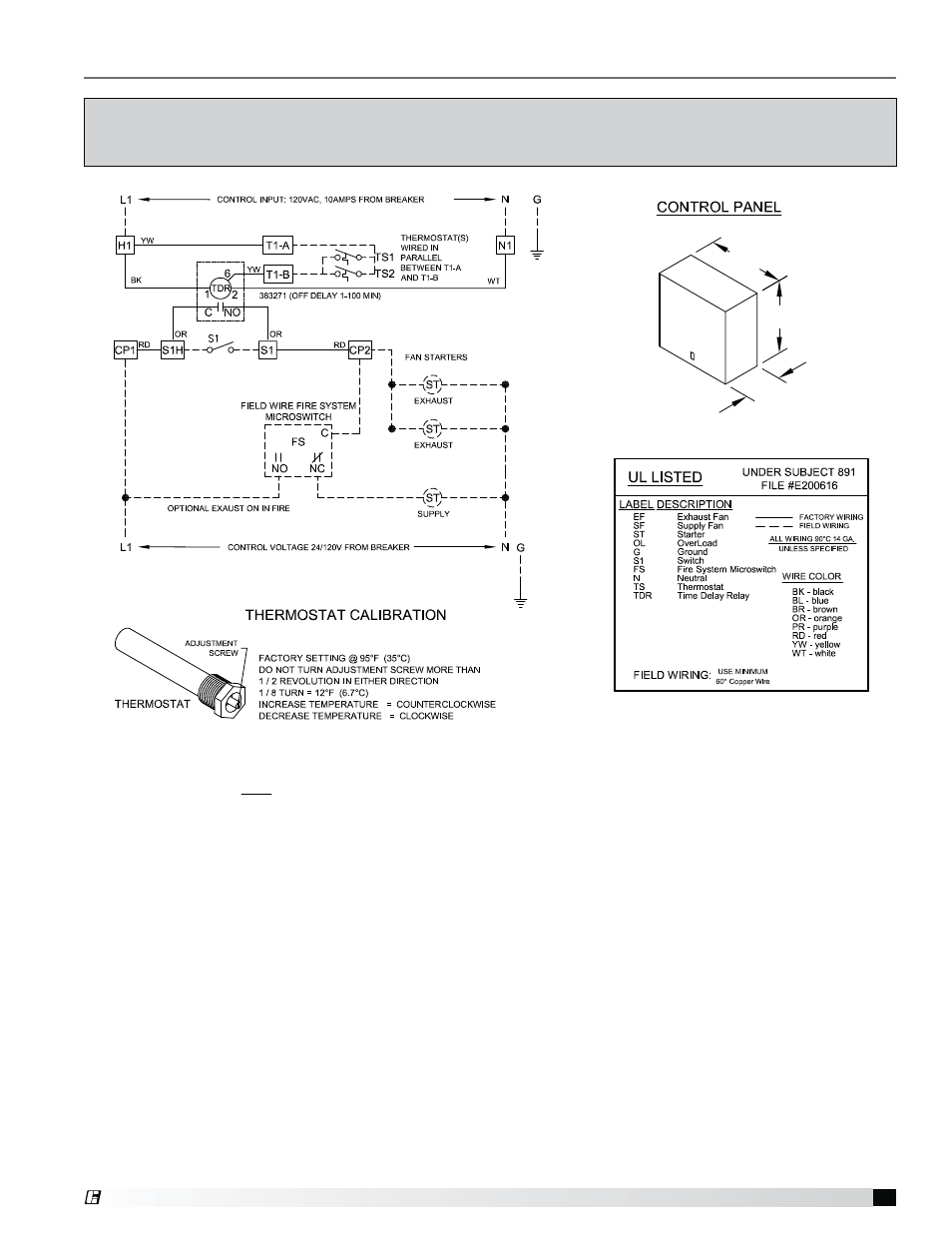
This Control Panel only provides control power to signal operation of supply and exhaust starters.
Starters are NOT provided by manufacturer. Starters to be provided by, wired and mounted by others.
8 inches
8 inches
4 inches
Control Circuit Diagram (Standard Control)
This is an example of a generic wiring diagram for standard control. It provides temperature interlock
function for two exhaust fans and one supply fan. (All starters provided by others, external to this control box).
®
See also other documents in the category Greenheck Equipment:
- VCD-40 Extension Pin Kit 316SS (475290) (2 pages)
- 331-2856, 332-2856 - Siemens 6 Actuator (454206) (2 pages)
- 331-2976, 332-2976 - Siemens 4 Actuator (454202) (2 pages)
- 331-4551, 332-4551 - Siemens 3 Actuator (454201) (2 pages)
- Adjustable Pressure Controller (468292) (3 pages)
- 7800 Series Relay Modules (12 pages)
- Standard Control - MSSC (476372) (4 pages)
- NFB Series Actuators External Mount (464236 IOM) (2 pages)
- GND Series External Mount (473723) (4 pages)
- Amplifier for 7800 Series Relay Module (8 pages)
- APEX Curbs (462831) (4 pages)
- AMD-xx-TD Transmitter (35 pages)
- Blade Seal Repalcement (HCDR Series) (1 page)
- VCD (463384) (12 pages)
- BAPI Zone Pressure Touch (ZPT) Sensor (6 pages)
- VCD (463384) (10 pages)
- Blade Seal Replacement (HCD Series) (2 pages)
- BR Series - Counterweight Adjustment (469420) (4 pages)
- Leakage Rated Ceiling Radiation Dampers (475063 IOM). (32 pages)
- Canopy Hoods (452413 IOM) (36 pages)
- Clean-Out Port Kit (472428) (1 page)
- Centrifugal (CSW, BIDW, AFDW), Industrial (IPA, IPO, IPW) and Filtered Supply (LSF) (463687) (12 pages)
- Close Indicator Switch for Fire Dampers (474050) (1 page)
- Concrete Floor with Steel Deck Supplement (463562) (1 page)
- CRD-3XX and CRD-7XX Series for SP fans (452832) (2 pages)
- VCD (463384) (8 pages)
- VCD (463384) (4 pages)
- Single Side Retaining Angle (52 pages)
- DG / DGX with Pilot Ignition (463555 IOM) (Pre-2008) (48 pages)
- DG / DGX with Direct Spark (470652) (40 pages)
- Digital Temperature Interlock (474750 IOM) (Pre November 2012) (8 pages)
- DGK (468695) (20 pages)
- DG / DGX with Pilot Ignition (463555 IOM) (Pre-2008) (52 pages)
- Double Gland Axle Seal Replacement (1 page)
- Dock Arm Kit (475367) (4 pages)
- Duct Heaters Series IDHB and IDHC (478052) (8 pages)
- EHH-601D, Channel Installation (474643) (10 pages)
- EHH-601D, Channel Installation with VCD-40 Damper (474644) (8 pages)
- EHH-601D, Flange/Sleeve Installation (474641) (8 pages)
- GM Series (468391) (4 pages)
- EHH-601D, Flange/Sleeve Installation with VCD-40 Damper (474642) (8 pages)
- El-O-Matic E and P Series (12 pages)
- Energy Recovery Filter Hood System (8 pages)
- ERV-582/120 Curbs (460988) (4 pages)
- ESD-635D, Chanel Installation (474639) (10 pages)