Greenheck Smoke Detector D4120 (Install) User Manual
Page 8
Three-Year
Limi
Ted
W
arran
TY
Sy
stem
Sensor
w
arr
ants
its
enclosed
pr
oduct
to
be
fr
ee
fr
om
defects
in
materials
and
w
orkmanship
under
normal
use
and
service
for
a
period
of
thr
ee
year
s
fr
om
date
of
manufactur
e.
Sy
stem
Sensor
mak
es
no
other
expr
ess
w
arr
anty
for
the
enclosed
pr
oduct.
No
agent,
repr
esentativ
e,
dealer
,
or
emplo
yee
of
the
Compan
y
has
the
authority
to
in
-
cr
ease
or
alter
the
obligations
or
limitations
of
this
W
arr
anty
.
The
Compan
y’
s
obligation
of
this
W
arr
anty
shall
be
limited
to
the
replacement
of
an
y
part
of
the
pr
oduct
which
is
found
to
be
defectiv
e
in
materials
or
w
orkmanship
under
normal
use
and
service
during
the
thr
ee
year
period
commencing
with
the
date
of
manufactur
e.
After
phoning
Sy
stem
Sensor’
s
toll
fr
ee
number
800-SENSOR2
(736-7672)
for
a
Return
A
uthorization
number
, send
defectiv
e
units
postage
pr
epaid
to:
Sy
stem
Sensor
, R
eturns
Department,
RA
#__________,
3825
Ohio
A
venue
,
St.
Charles
,
IL
60
174.
Please
include
a
note
describing
the
malfunction
and
suspected
cause
of
failur
e.
The
Compan
y
shall
not
be
obligated
to
replace
units
which
ar
e
found
to
be
defectiv
e
because
of
damage
,
unr
easonable
use
,
modifications
, or
alter
ations
occurring
after
the
date
of
manufactur
e.
In
no
case
shall
the
Compan
y
be
liable
for
an
y
consequential
or
incidental
damages
for
br
each
of
this
or
an
y
other
W
arr
anty
, e
xpr
essed
or
implied
whatsoe
ver
, e
ven
if
the
loss
or
damage
is
caused
by
the
Compan
y’
s
negligence
or
fault.
Some
states
do
not
allo
w
the
ex
clusion
or
limitation
of
incidental
or
consequential
damages
, so
the
abo
ve
limitation
or
ex
clusion
ma
y
not
apply
to
you.
This
W
arr
anty
giv
es
you
specific
legal
rights
, and
you
ma
y
also
ha
ve
other
rights
which
vary
fr
om
state
to
state
.
Please
refer
to
inser
t
for
the
Limitations
of
Fir
e
Alar
m
Systems
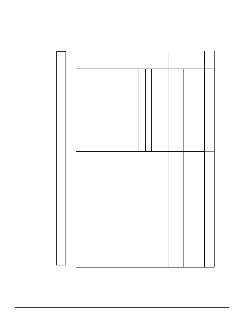
Sensor
D4S
Power Board
D4P120
At power-up or reset at the panel, th
e
sensor will take approx 45 seconds
to initialize.
Also occurs if the sensor
has been removed and restored in
the base in the sensor housing.
RED Blink every 5
seconds
Alternatin
g
Green/ambe
r
every 1 second
Supervisory rela
y:
Te
rminals 3 and 14 are open.
Alarm Relay
: T
erminals 4 and 5 are open.
Aux Rela
y does not switch states:T
erminals 6 and 16 are closed,
Te
rminals 8 and 18 are closed
Sensor is missing during the seven
minute tamper Dela
y, if selected.
Of
f
Alternatin
g
Green/ambe
r
every 1 second
Supervisory rela
y:
Te
rminals 3 and 14 are closed
Alarm Rela
y:
Te
rminals 4 and 5 are open.
Aux Relay
does not switch states:T
erminals 6 and 16 are closed,
Te
rminals 8 and 18 are closed
Maintenance
Sensor D4S is outside it's UL
approved sensitivity limits and needs
to be cleaned or replaced
.
RED Blink every 5
seconds
Amber Blink
every 5 seconds
Supervisory rela
y:
Te
rminals 3 and 14 are open.
Alarm Relay
: T
erminals 4 and 5 are open.
Aux Relay
does not switch states:T
erminals 6 and 16 are closed,
Te
rminals 8 and 18 are closed
.Unit loses Power
Of
f
O
ff
.Cover
Ta
mper Delay times out
Green Blink every 5
seconds
Amber soli
d
.Wiring Problems between the
Sensor and the Power Boar
d
Of
f
A
mber soli
d
.Mismatch between the number of
sensors connected and the Dip
Switch setting
1 sensor connected,2 selected
Green blink every 5
seconds on first
sensor
.
No second sensor
.
LED1 Green
blink every 5
seconds
LED2
Amber
solid
2 sensors connected,1 selected
Green blink every 5
seconds on first
sensor
.
LED's of
f on second
sensor
LED1 Green
blink every 5
seconds
LED2
Amber
solid
Alar
m
Unit detects smok
e
S
olid Re
d
S
olid Red
Supervisory rela
y:
Te
rminals 3 and 14 are closed
Alarm Rela
y:
Te
rminals 4 and 5 are closed.
Aux Relay
switches states:
Te
rminals 6 and 16 are open,
Te
rminals 8 and 18 are open
Standby
Unit has Power and it is not in
initialization,
T
rouble, Maintenance or
Alarm.
Green Blink every 5
seconds
Green Blink
every 5 seconds
Supervisory rela
y:
Te
rminals 3 and 14 are closed
Alarm Relay
: T
erminals 4 and 5 are open.
Aux Rela
y does not switch states:
Te
rminals 6 and 16 are closed,
Te
rminals 8 and 18 are closed
LED Statu
s
Status
Descriptio
n
Status of Relays
Supervisory rela
y:
Te
rminals 3 and 14 are open.
Alarm Relay:
T
erminals 4 and 5 are open.
Aux Rela
y does not switch states with no shutdown on
T
rouble selected:
Te
rminals 6 and 16 are closed.
Te
rminals 8 and 18 are closed.
Aux Relay
Switches states with shutdown on
T
rouble selected:
Te
rminals 6 and 16 are open,
Te
rminals 8 and 18 are open
Tr
ouble
Sensor
Initialization
Tab
Le 3.
d
e
Tec
Tor S
Ta
Tu
S
indica
Tion
NO
TE:
Ther
e
ar
e
tw
o
LED’
s
on
the
Po
w
er
boar
d
D4P12
0,
each
indicating
the
Status
of
the
tw
o
sensor
s
connected.
When ther
e is only one sensor connected, LED2 will r
emain off.
NO
TE: If an
y other visual indication is noted contact S
ystem Sensor technical support at 1-800-SENSOR2.
SS-300-000
8
I56-2967-002R
©2008 System Sensor