Greenheck Smoke Detector D4120 (Install) User Manual
Page 6
SS-300-000
6
I56-2967-002R
[10] deTecTor STaTuS indicaTion
Detector Staus is indicated by the LED sensor, and the correcsponding LED
on the power board. The power board has two separate LED’s to indicate
the status of each sensor connected to it. Refer to Table 3 on page 8 for more
details.
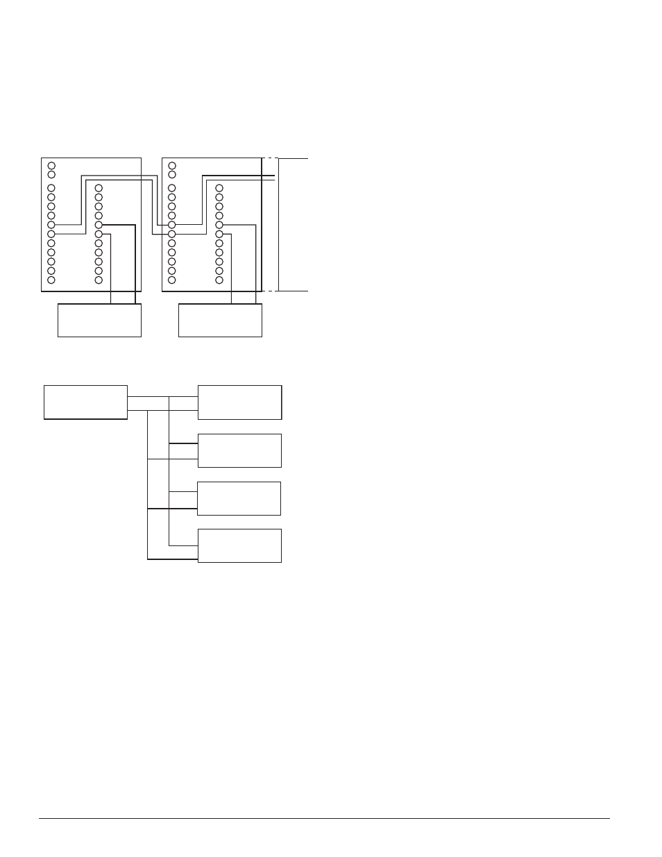
[11] inTerconnecTion (muLTiPLe fan ShuT doWn)
When using the interconnect feature, an alarm from an initiating device will
switch the Aux Relays on the other devices interconnected.
figure 8. muLTiPLe fan ShuTdoWn
(inTerconnecTion of d4120’S):
DETECTOR 1
120 VAC
D4120
C, AUX A
NC, AUX A
50
DET.
MAX.
INT/AUX–
INT+
SYSTEM CONTROL
POWER, FAN
CONTROL OR
THERMOSTAT
SYSTEM CONTROL
POWER, FAN
CONTROL OR
THERMOSTAT
12
1
–
+
2
11
15
20
19
9
10
16
6
5
13
3
14
17
8
18
7
4
DETECTOR 2
120 VAC
D4120
C, AUX A
NC, AUX A
INT/AUX–
INT+
12
1
–
+
2
11
15
20
19
9
10
16
6
5
13
3
14
17
8
18
7
4
H0552-00
figure 9. muLTiPLe fan ShuTdoWn
(inTerconnecTion of d4120 To dh100acdc):
DH100ACDC
DH100ACDC
D4120
D4120
D4120
H0617-00
[11.1] imPorTanT inTerconnecTion noTeS:
When using the interconnect feature, all interconnected units must be
•
powered using the same independent supply.
Polarity must be maintained throughout the interconnect wiring.
•
Connect the INT+ terminal on unit 1 to the INT+ terminal on unit 2
and so on. Similarly, connect the INT/AUX- terminal on unit 1 to the
INT/AUX- terminal on unit 2 and so on.
Up to 50 D4120 units may be interconnected.
•
Up to 10 DH100ACDC units may be interconnected. Please note that
•
each of the 9 DH100ACDC units interconnected can be substituted by
three D4P120 units. Therefore, when using the interconnect feature a
single DH100ACDC can drive either 9 DH100ACDC’s or 27 D4120 units.
NOTE: Alarm can be reset only at the initiating device and not at the devices
interconnected.
[12] VerificaTion of oPeraTion
[12.1] fieLd SeLecTabLe SeTTingS
Verify dip switch settings as per Table 2 on Page 5.
[12.2] PoWering The uniT
Apply 24 VDC power to 9 and 10 terminals on the D4P120 or apply 120 VAC on
terminals named 120VAC. See Figure 7 and electrical specifications for details.
[12.3] Perform deTecTor check
VERIFY STANDBY AND TROUBLE TEST per Table 3 on page 8. The use of a
remote accessory for visible indication of power and alarm is recommended.
NOTE: If an instantaneous tamper delay is selected a trouble may be indicated
with the cover installed.
[12.4] SenSiTiViTY VerificaTion
The sensitivity of the sensor is confirmed to be operating within its allowable
range each time the sensor and power board LEDs blink green every 5 sec-
onds. Note in a maintenance condition the sensor LEDs will blink red every 5
seconds and power board will blink amber as depicted in Table 3 on page 8.
The maintenance condition indicates that the sensor is operating outside its
original factory preset sensitivity and shall be cleaned or replaced. See Section
9 for reference. This is a valid UL test.
[12.5] deTecTor cLeaning ProcedureS
Notify the proper authorities that the smoke detector system is undergoing
maintenance, and that the system will temporarily be out of service. Disable
the zone or system undergoing maintenance to prevent unwanted alarms and
possible dispatch of the fire department.
[12.5.1] aLarm TeSTS
1a. Test/Reset Button - Press and hold the test button located on the power
board cover for at least 2 seconds.
OR
1b. M02-04-00 Magnet Test - Place the painted surface of the magnet onto
the MAGNET TEST location on the sensor cover of unit (Figure 1).
OR
1c. Remote Test Accessory - See list on page 1.
The red alarm LED on the sensor and the power board should latch on,
as should any accessories (i.e. RA400Z, RTS451). Verify system control
panel alarm status and control panel execution of all intended auxiliary
functions (i.e fan shutdown, damper control, etc.).
2. The detector must be reset by the system control panel, front cover Test/
Reset button, or remote accessory.
3. To reset using the Test/Reset button on the power board cover simply
Press and release.
4. Verify airflow test per Section 7 has been performed.
[12.5.2] Smoke reSPonSe TeSTS
To determine if smoke is capable of entering the sensing chamber, visually
identify any obstructions. Plug the exhaust and sampling tube holes to pre-
vent ducted air from carrying smoke away from the detector head, then blow
smoke such as cigarette, cotton wick, or punk directly at the head to cause
an alarm. REMEMBER TO REMOVE THE PLUGS AFTER THIS TEST, OR THE
DETECTOR WILL NOT FUNCTION PROPERLY.
[12.5.3] Smoke enTrY uSing aeroSoL Smoke
This test is intended for low-flow systems (100-500 FPM). If the air speed is
greater than 500 FPM, use a conventional manometer to measure differential
pressure between the sampling tubes, as described in Section 7.1.
Drill a
1
⁄
4
inch hole 3 feet upstream from the duct smoke detector. With the air
handler on, measure the air velocity with an anemometer. Air speed must be
at least 100 FPM. Spray aerosol smoke* into the duct through the
1
⁄
4
inch hole
for five seconds. Wait two minutes for the duct smoke detector to alarm. If the
duct smoke detector alarms, air is flowing through the detector. Remove the
duct smoke detector cover and blow out the residual aerosol smoke from the
chamber and reset the duct smoke detector. Use duct tape to seal the aerosol
smoke entry hole.
*Aerosol smoke can be purchased from Home Safeguard Industries, model
25S Smoke Detector Tester, Malibu, CA. Phone: 310/457-5813 and Chekkit
Smoke Detector Tester model CHEK02 and CHEK06 available from SDi. When
used properly, the canned smoke agent will cause the smoke detector to go
into alarm. Refer to the manufacturer’s published instructions for proper use
of the canned smoke agent.