Volt meter fluke model 87 or equivalent – Greenheck Smoke Detector D4120 (Install) User Manual
Page 4
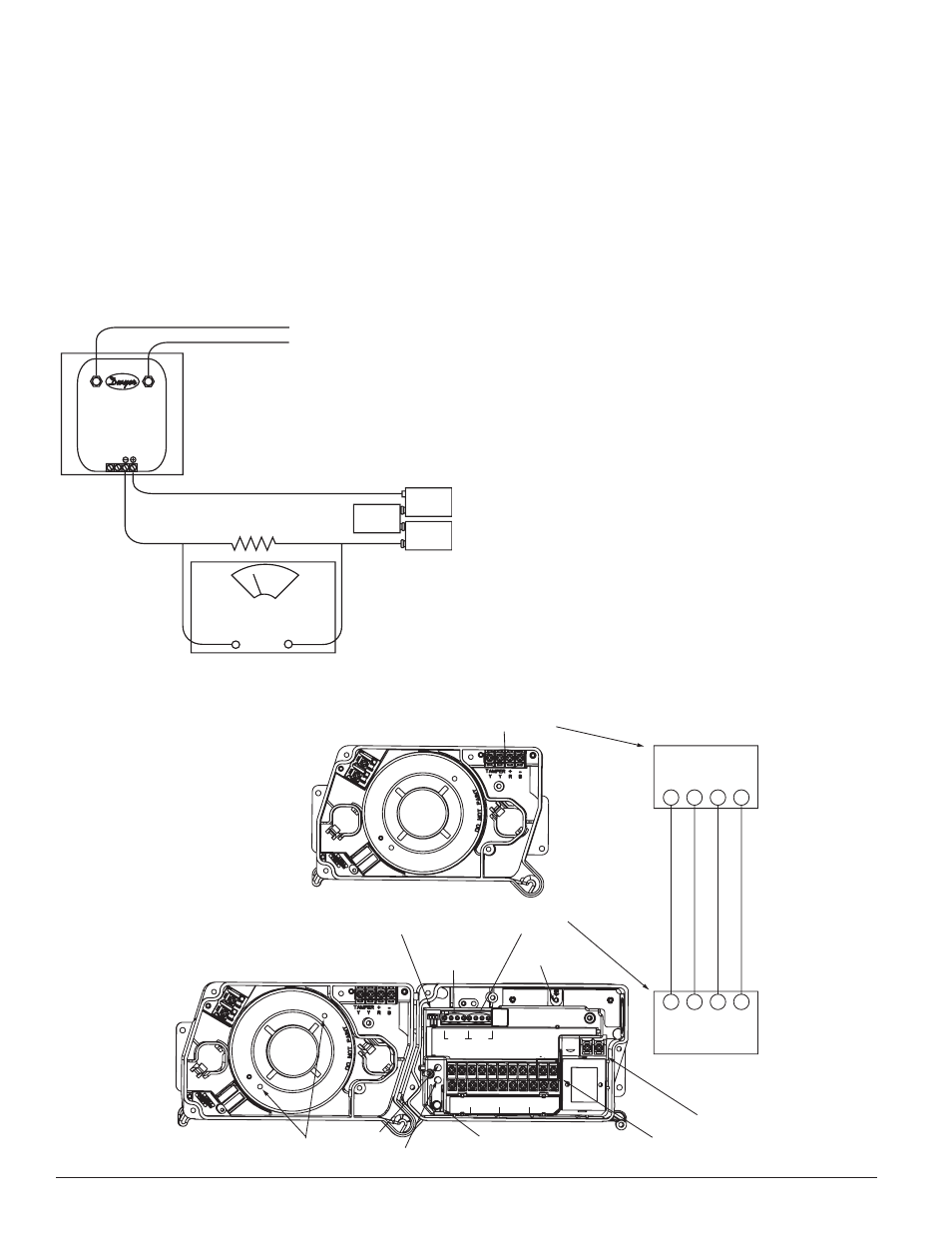
[7.2] LoW fLoW air fLoW TeST uSing dWYer SerieS 607
differenTiaL PreSSure TranSmiTTer
Verify the air speed of the duct using an anemometer. Air speed must be at
least 100 FPM. Wire the Dwyer transmitter as shown in Figure 5. Connect the
leads of the meter to either side of the 1000Ω resistor. Allow unit to warm up
for 15 seconds. With both HIGH and LOW pressure ports open to ambient air,
measure and record the voltage drop across the 1000Ω resistor (measurement
1), 4.00 volts is typical. Using flexible tubing and rubber stoppers, connect the
HIGH side of the transmitter to the sampling tube of the duct smoke detec-
tor housing, and the LOW side of the transmitter to the exhaust tube of the
duct smoke detector housing. Measure and record the voltage drop across the
1000Ω resistor (measurement 2). Subtract the voltage recorded in measure-
ment 1 from the voltage recorded in measurement 2. If the difference is greater
than 0.15 volts, there is enough air flow through the duct smoke detector for
proper operation.
[8] fieLd Wiring inSTaLLaTion guideLineS
All wiring must be installed in compliance with the National Electrical Code
and the local codes having jurisdiction. Proper wire gauges should be used.
The conductors used to connect smoke detectors to control panels and acces-
sory devices should be color-coded to prevent wiring mistakes. Improper con-
nections can prevent a system from responding properly in the event of a fire.
For signal wiring, (wiring between interconnected detectors or from detectors
to auxiliary devices), it is recommended that single conductor wire be no
smaller than 18 gauge.
Smoke detectors and alarm system control panels have specifications for al-
lowable loop resistance. Consult the control panel manufacturer’s specifica-
tions for the total loop resistance allowed for the particular control panel being
used before wiring the detector loop.
[8.1] Wiring inSTrucTionS
The D4120 and D4P120 detectors are designed for easy wiring. The housing
provides a terminal strip with clamping plates. The D4S housing provides 4
wiring terminals with clamping plates. Wiring connections are made by slid-
ing the bare end of the wire under the plate, and tightening the clamping plate
screw. See Figure 7 on page 5 for system wiring.
[8.2] SenSor 2 inSTaLLaTion/Wiring
The power board is capable of controlling a second housed sensor. The second
sensor, model D4S, can be wired to the power board per the following:
1. Connect wires to the four wire terminals in the corner of the D4S sensor
housing designated as Tamper (Y,Y), +R, and –B. Route wires through the
conduit openings in the sensor housing and D4120 power board housing.
2. Connect the opposing ends of the wires to the terminal connections
marked “Sensor 2” on the Power board. See Figure 6 for reference. En-
sure that wires are connected to the appropriate terminal locations. A
No. 0 or 1 phillips screwdriver should be used for terminal connection.
The tamper terminals are not polarity sensitive.
3. Adjust the middle dip switch on the power board to indicate (2) sensors
as shown in Figure 6.
4. The D4S can only be used with new InnovairFlex models and is not com-
patible with previously sold detectors.
HIGH
LOW
9 VOLT
BATTERY
9 VOLT
BATTERY
9 VOLT
BATTERY
TO SAMPLING TUBE
TO EXHAUST TUBE
DIFFERENTIAL
PRESSURE
TRANSMITTER
MODEL #607-01
15 TO 36
VDC SUPPLY
1000 OHM 5%
1 WATT RESISTOR
VOLT METER FLUKE
MODEL 87 OR
EQUIVALENT
+
–
figure 5. Procedure for VerifYing air fLoW LeSS Than 500 fPm:
H0163-01
SS-300-000
4
I56-2967-002R
FIELD SELECTABLE
DIP SWITCHES
TEST/RESET
BUTTON
POWER
BOARD LED 2
SENSOR
LEDs
GROUND
SCREW
SENSOR #1
TERMINALS
D4120
CO-LOCATED
WIRING TERMINALS
24V
A
C
/DC,
10
24V
A
C
/DC,
9
A
U
X OUT +,
19
A
U
X OUT -,
20
INT/
A
U
X-
, 1
INT+
, 12
ALARM,
15
R
TEST
, 11
R RESET
, 2
A
C
C
-
A
C
C
+
120 VAC
B
-
R
+
Y
Y
B
-
R
+
Y
Y
TAMPER
TAMPER
SENSOR 1
SENSOR 2
OFF/ON
TRBL SHUTDN
1/2 SENSORS
7/0 MIN
TMPR DEL
A
Y
7,
NO
18
, C
AUX B
8,
NC
17
, NO
AUX A
6,
C
16
, NC
14
, N0
3,
C
13
, NC
5,
NO
SUP
ALARM
4,
C
D4S
SENSOR ONLY
SENSOR #2
TERMINALS
TAMPER
Y Y R B
Y Y R B
+ –
TAMPER
+ –
SENSOR 2
D4120
D4S
NOTE: IF USING (2) D4S
SENSOR ONLY
COMPONENTS WITH
MODEL D4P120 POWER
BOARD COMPONENT, USE
SENSOR #1 TERMINALS
AND WIRE IN SAME
MANNER AS SHOWN FOR
SENSOR #2.
POWER
BOARD LED 1
120
VAC INPUT
24 VAC/
DC INPUT
H0557-01
figure 6. oPTionaL SenSor 2 configuraTion and Wiring: