Greenheck Modular Small Cabinet Fan (Model MSCF) (462888) User Manual
Page 3
3
Modular Small Cabinet Fan
®
Table of Contents
Installation
Unit Layout . . . . . . . . . . . . . . . . . . . . . . . . . . . . . . .3
Mounting / Hanging Instructions . . . . . . . . . . . . . 4
Mounting Dimensions . . . . . . . . . . . . . . . . . . . . . . 5
Dimensions / Weights . . . . . . . . . . . . . . . . . . . . . . 6
Filter Sizes / Quantity . . . . . . . . . . . . . . . . . . . . . . 6
Coil Dimensions . . . . . . . . . . . . . . . . . . . . . . . . .7-9
Start-Up
System Start-Up . . . . . . . . . . . . . . . . . . . . . . . . . 10
Troubleshooting
Blower . . . . . . . . . . . . . . . . . . . . . . . . . . . . . . . . . 10
Motor Overamps . . . . . . . . . . . . . . . . . . . . . . . . . 10
Insufficient / Too Much Airflow . . . . . . . . . . . . . . 10
Excessive Noise or Vibration . . . . . . . . . . . . . . . 10
Start-Up
Coil Module . . . . . . . . . . . . . . . . . . . . . . . . . . .12-13
Drain Pan / Drain Trap . . . . . . . . . . . . . . . . . . . . 13
Installation
Electric Heater . . . . . . . . . . . . . . . . . . . . . . . . . . . 14
Operation
Electric Heater . . . . . . . . . . . . . . . . . . . . . . . . . . . 15
Maintenance
Fan . . . . . . . . . . . . . . . . . . . . . . . . . . . . . . . . . . . . 16
Coil . . . . . . . . . . . . . . . . . . . . . . . . . . . . . . . . . . . . 16
Drain Pan . . . . . . . . . . . . . . . . . . . . . . . . . . . . . . . 16
Reference
Start-Up Documentation . . . . . . . . . . . . . . . . . . . 17
Optional Ladder Diagrams . . . . . . . . . . . . . . .18-19
Maintenance Log . . . . . . . . . . . . . . . . . .Backcover
Our Comittment . . . . . . . . . . . . . . . . . . . .Backcover
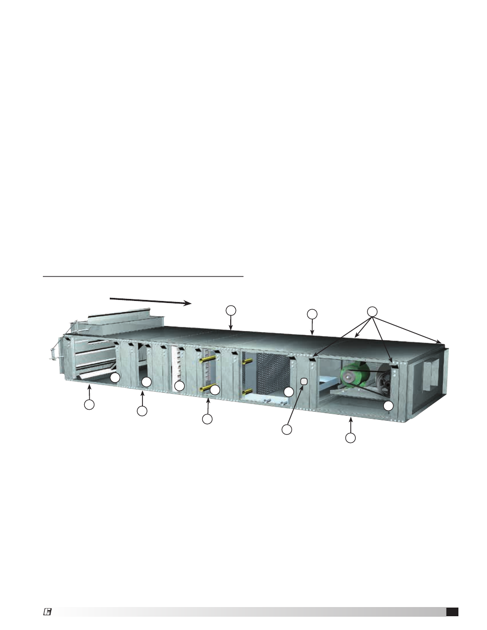
Unit Layout
1. Fan and Cabinet Section
2. Cooling Section
• Chilled Water
• DX Coils
3. Heating Section
• Hot Water
• Steam Coils
4. Filter Section
Filter may be mounted in Mixing Box Section
5. Plenum Section
6. Mixing Box Section
7. Lifting Lugs
Four (4) lifting lugs for each section
8. Side Access Panels
Right and left access to each section
(image shows panels removed)
9. 7/8-inch knockout is provided for the
recommended electrical wiring penetration or
disconnect switch.
1
3
6
2
4
5
Airflow
7
8
8
8
8
8
8
9