Radial gap, overlap and wheel alignment, Wheel rotation, Radial gap and alignment – Greenheck USF and CSW (479870) User Manual
Page 9
Utility and Centrifugal Fans
9
®
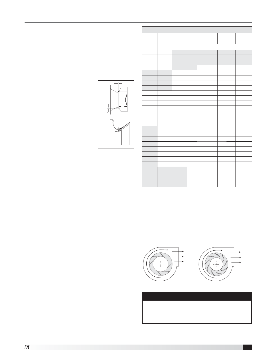
Wheel Rotation
Rotation direction of the wheel is critical and incorrect
rotation will result in reduced air performance,
increased motor loading and possible motor burnout.
Check wheel rotation by momentarily energizing the
unit and noting if rotation is in the same direction as
the airflow at the outlet and conforms to the rotation
decal affixed to the unit.
Wheels as viewed from the drive side:
NOTE
Model USF and CSW units should be operated only
when attached to the system for which they were
designed. Without proper system static pressure,
the motor could be overloaded.
Airflow
R
o
ta
ti
o
n
R
o
ta
ti
o
n
Airflow
Backward Inclined
Airfoil
Wheels must rotate freely and not rub on the inlet
cone. Model USF and CSW wheels overlap the inlet
cone. Refer to the table for the proper dimension.
Radial Gap and Alignment
Efficient fan performance can be maintained by having
the correct radial gap, overlap and wheel alignment.
These items should be checked after the fan has been
in operation for 24 hours and before start-up when the
unit has been disassembled.
Radial Gap: Adjust inlet cone
position such that the radial gap
between the wheel cone and inlet
cone is evenly distributed around
the wheel.
Radial gap is adjusted by
loosening the inlet cone/ring bolts
and centering the cone/ring on the
wheel. If additional adjustment is
required to maintain a constant
radial gap, loosening the bearing
bolts and centering the wheel is
acceptable as a secondary option.
Overlap: Overlap is adjusted by loosening the wheel
hub from the shaft and moving the wheel to the
desired position along the shaft.
The transition between the inlet cone and wheel
should be as shown; there is a smooth feel to the
profile when moving from one component to the other.
Method for Centering Wheel: On belt drive units,
centering can be accomplished by (a) loosening
the inlet cone bolts to move the inlet cone or by (b)
loosening the bearings in order to move the shaft.
Wheel and inlet cone overlap can be adjusted by
loosening the wheel hub set screws and moving the
wheel to the desired position. Tighten all fasteners
and set screws securely and realign drive pulleys after
adjustment.
Wheel
Cone
Radial
Gap
Radial
Gap
Overlap
A
Straight
Edge
Straight
Edge
Inlet
Cone
Inlet
Cone
Radial Gap, Overlap and Wheel Alignment
Radial Gap and Overlap Dimensions
USF-200 USF-300 USF-400 CSW
A
Overlap
Overlap
Tolerance
inches (mm)
206
306
-
-
-
207
307
-
-
-
208
308
-
-
-
210
310
4
15
⁄
16
(125)
3
⁄
8
(10)
1
⁄
8
(3)
407
7
1
7
⁄
16
(37)
2
15
⁄
32
(63)
1
⁄
8
(3)
408
8
2
11
⁄
16
(68)
1
7
⁄
32
(31)
1
⁄
8
(3)
409
9
3
11
⁄
16
(94)
7
⁄
32
(6)
1
⁄
8
(3)
410
10
3
11
⁄
16
(94)
7
⁄
32
(6)
1
⁄
8
(3)
212
312
412
12
4
1
⁄
4
(108)
11
⁄
32
(9)
1
⁄
8
(3)
213
313
413
13
4
11
⁄
16
(119)
3
⁄
8
(10)
1
⁄
8
(3)
215
315
415
15
5
3
⁄
16
(132)
7
⁄
16
(11)
1
⁄
8
(3)
216
316
416
16
5
3
⁄
4
(146)
7
⁄
16
(11)
1
⁄
8
(3)
218
318
418
18
6
3
⁄
8
(162)
15
⁄
32
(12)
1
⁄
8
(3)
220
320
420
20
7
(178)
1
⁄
2
(13)
3
⁄
16
(5)
222
322
422
22
7
13
⁄
16
(198)
17
⁄
32
(13)
3
⁄
16
(5)
324
424
24
8
5
⁄
8
(219)
9
⁄
16
(14)
1
⁄
4
(6)
327
427
27
9
7
⁄
16
(240)
11
⁄
16
(17)
1
⁄
4
(6)
330
430
30
10
9
⁄
16
(268)
11
⁄
16
(17)
3
⁄
8
(10)
333
433
33
11
7
⁄
16
(291)
15
⁄
16
(24)
3
⁄
8
(10)
336
436
36
12
3
⁄
4
(324)
15
⁄
16
(24)
3
⁄
8
(10)
340
440
40
14
3
⁄
16
(360)
29
⁄
32
(23)
3
⁄
8
(10)
344
444
44
15
9
⁄
16
(395) 1
1
⁄
8
(29)
3
⁄
8
(10)
349
449
49
17
1
⁄
8
(435)
1
1
⁄
4
(32)
1
⁄
2
(13)
54
18
13
⁄
16
(478) 1
17
⁄
32
(39)
1
⁄
2
(13)
60
20
15
⁄
16
(532) 1
9
⁄
16
(40)
1
⁄
2
(13)
66
22
7
⁄
8
(581) 1
29
⁄
32
(48)
1
⁄
2
(13)
73
25
1
⁄
2
(648) 1
29
⁄
32
(48)
1
⁄
2
(13)