Operation and unit start-up – Greenheck TBI-FS/TBI-CA/TDI (460983) User Manual
Page 5
Operation and Unit Start-Up
Electrical Connections
The electrical supply must be compatible with the
fan motor voltage, phase and amperage capacity.
The electrical supply line must be properly fused and
conform to local and national electrical codes.
For direct drive units, the electrical supply may be
routed internally and exit through a hole provided in the
fan housing if an optional service disconnect switch is
provided.
For belt drive units, the electrical supply line may be
routed internally and exit the fan housing through a hole
provided below the belt tube opening. The electrical
supply line should then be either: (1) connected to an
optional service disconnect switch, or (2) wired directly
to the motor.
For belt drive units in continuous high
temperature installations, the electrical supply
must be kept out of the airstream. This means bringing
the supply lines off the roof deck not through the fan.
The electrical supply line should then be either: (1)
connected to an optional service disconnect switch, or
(2) wired directly to the motor.
The supply wires are then connected to an
optional
safety disconnect switch (if supplied) or wired directly to
the motor.
For belt drive units in emergency smoke removal
installations, the electrical supply must be kept out of
the airstream. They may also require an isolated power
supply so that if power is cut to the building in the event
of a fire, the fan will continue to operate. Check the
local and national electrical codes for emergency smoke
removal fans.
Pre-Start-Up Checks
1. Check all fasteners for tightness. This includes motor
bolts, bearing bolts, and any set screws or locking
collars attaching the propeller to the shaft and shaft
to the bearings.
If roof upblast configuration, lift the butterfly dampers
to verify they open and close without binding.
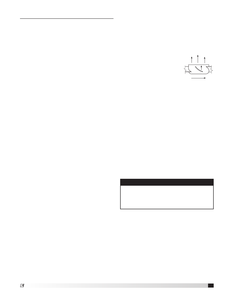
2. Rotate the propeller by hand
to ensure it turns freely and
does not rub on the fan tube.
Propeller rotation should always
be checked by turning the unit
on momentarily. Rotation should
be in the same direction as the
rotation decal affixed to the unit. Actual direction
of rotation will vary by model. To reverse rotation
on three phase installations, simply interchange
two of the three electrical leads. For single phase
installations, follow the wiring diagram located on the
motor.
3.
Belt Drive Fan RPM - adjustable motor pulleys are
preset at the factory for the specified fan RPM. Fan
speed can be increased by closing or decreased by
opening the adjustable pulley. Multi-groove variable
pitch pulleys must be adjusted an equal number of
turns open or closed.
4.
Belt Drive Roof Upblast Fan RPM - adjustable
motor pulley on motors less than 10 HP is preset
at the factory to the customer-specified RPM. Fan
speed can be increased or decreased by adjusting
the pitch diameter of the motor pulley. Multi-groove
variable pitch pulleys must be adjusted an equal
number of turns open. Motors 10 HP and larger will
have a constant speed pulley.
NOTE
Any change, increase or decrease, in fan speed
can represent a substantial increase in horsepower
required from the motor. Always check motor load
amperage and compare to nameplate rating when
changing fan speed.
Rotation
5
Tubular Inline Fans
®