Typical installations – Greenheck TBI-FS/TBI-CA/TDI (460983) User Manual
Page 4
A
B
C
B
D
A
C
Optional
Mounting
Rails
Optional
Motor at 3 or 9 o’clock position
Mounting
Rails
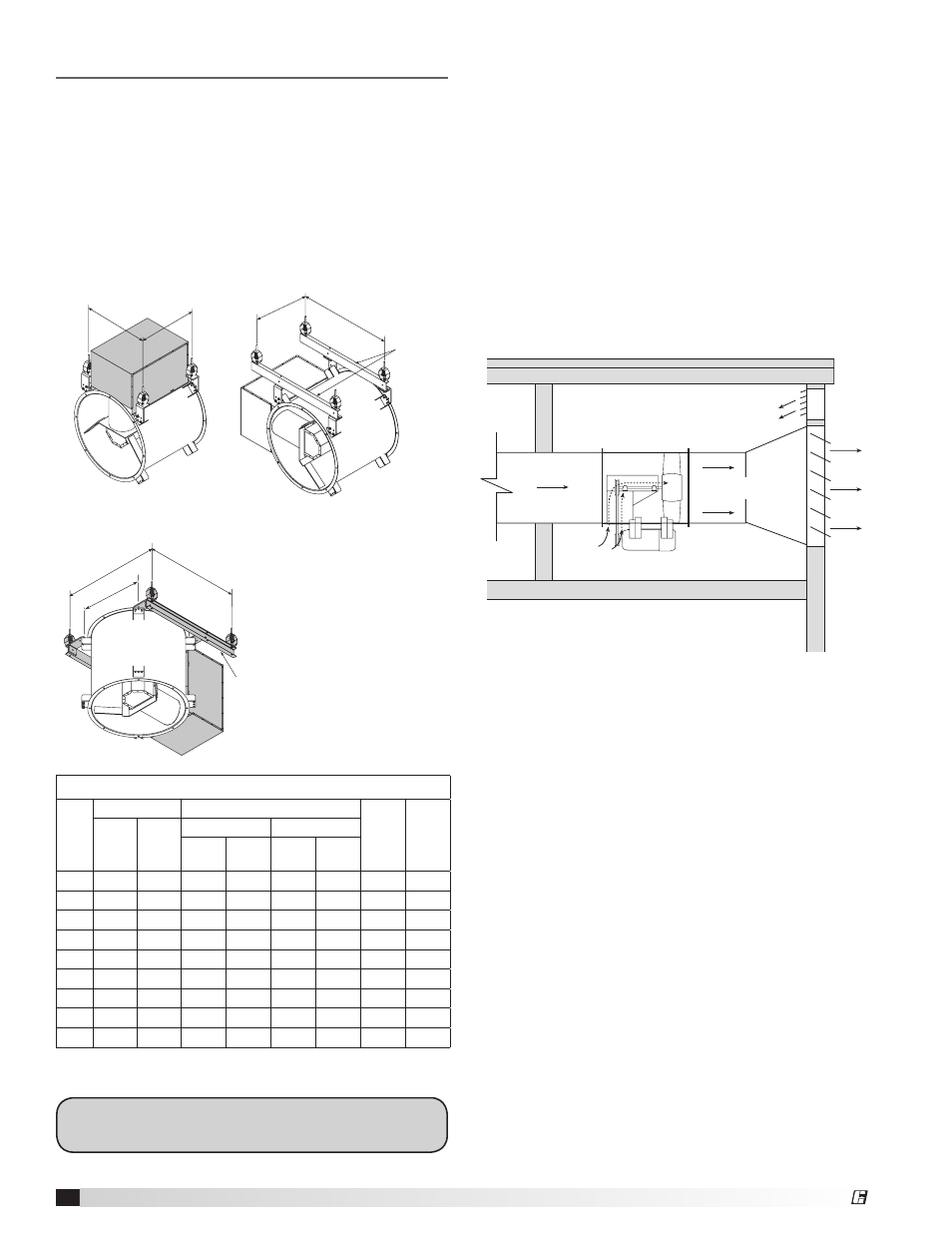
Continuous Duty and Emergency Exhaust
TBI-FS with optional high temperature construction
are factory-modified for operation in high temperature
continuous duty applications. With propeller on the
discharge end of the fan, negative pressure is created in
the belt tube during operation. Ambient air is drawn in
through the belt tube and cools the belts and bearings.
For the greatest amount of internal cooling, discharge
static pressure should be kept to a minimum while
keeping most of the pressure on the inlet side. Locate
the fan at ends of the duct runs and near the discharge
point in the system. This set-up will promote the
ambient air cooling effect.
Airflow
Duct to heat source
Ambient temperature
not to exceed 120°F
Minimum duct
at discharge
Wall and/or ceiling should enclose
fan when used for emergency heat
and smoke exhaust.
Roof
Cooling air for
drives and
bearings
Typical Installations
With Mounting Brackets
Following are typical mounting installations for models
with mounting brackets. Diagrams show dimensions for
ceiling hung installations. The dimensions for floor or
base mount installations are mirror images of these.
For TBI models with motor in the 3 or 9 o’clock position
or vertical installations, additional mounting rails are
recommended. Mounting rail dimensions are shown for
field fabrication.
A
B
C
B
D
A
C
Optional
Mounting
Rails
Optional
Motor at 3 or 9 o’clock position
Mounting
Rails
Mounting Hole Locations
Fan
Size
A
B
C
Belt
Drive
D
Belt
Drive
Belt
Drive
Direct
Driect
Belt Drive
Direct Drive
Level
3
Level
4/5
Level
3
Level
4/5
18
17.63 17.63 17.38 21.38 13.38 21.38 26.00 28.00
20
19.00 19.00 17.38 22.38 14.38 21.38 28.50 29.25
24
21.88 21.88 18.38 23.38 14.38 21.38 33.00 33.75
30
26.13 26.13 19.38 28.38 16.38 25.88 37.00 38.75
36
30.50 30.50 21.88 26.88 13.88 23.38 44.00 47.00
42
34.75 34.75 22.88 31.88 19.88 26.38 50.00 51.25
48
42.00 42.00 25.38 36.38 19.38 31.38 56.00 61.00
54
46.75 46.75 29.88 40.38
NA
31.38 62.00 65.50
60
51.00 51.00 32.38 41.38
NA
31.38 71.00 70.00
Dimensions shown are in inches.
Horizontal
Vertical
To determine unit level, refer to the fan nameplate.
Example TBI-3L42 (level 3) or TBI-4H30 (level 4)
4
Tubular Inline Fans
®