Lifting, Effects of installation on performance, Lifting point (4 places) 3 – Greenheck TBI-FS/TBI-CA/TDI (460983) User Manual
Page 3
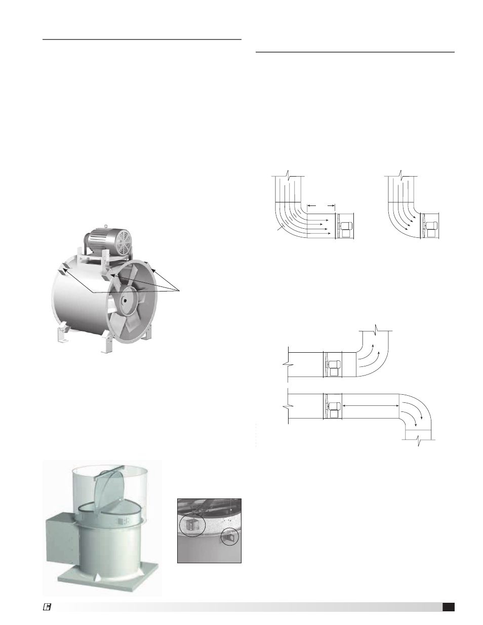
Lifting
Fans should not be lifted by the motor, motor shaft,
motor cover, belt guard, tie down points, belt tube,
damper frame, windband, or fan accessories.
Flanged Housing Only
Use a minimum of four bolt holes, two per flange, or
attach two suitable chains / straps around the entire fan
housing, one near each duct flange when lifting large
horizontal fans. Secure the fan housing to prevent the
weight of a top or side mounted motor from rotating the
housing while being lifted.
For vertical hanging installations, attach a suitable lifting
device to the fan housing or inlet/outlet flange.
With Mounting Brackets
Fans are to be rigged by either the optional brackets
provided or by the skid when a forklift is used. Slings
can be attached as described above or to mounting
brackets located at the ends of the fan housing.
Roof Upblast
Attach a suitable chain or strap to the four (4) windband
gussets located between the butterfly damper section of
the fan and the exterior windband
unless welded lifting
lugs are provided on fan housing. Carefully lift the fan to
the roof curb and install fasteners in all holes provided
in the unit base. The windband need not be removed for
the lifting operation. A spreader bar is recommended to
prevent damage to the damper section when lifting.
Effects of Installation on
Performance
Any installation with inlet or discharge configurations
that deviate from these recommendations may result in
reduced fan performance. Restricted or unstable flow
at the fan inlet can cause pre-rotation of incoming air or
uneven loading of the fan propeller yielding large system
losses and increased sound levels. Free discharge or
turbulent flow in the discharge ductwork will also result
in system effect losses.
The most common inlet and discharge conditions which
affect fan performance are:
Installation of a duct turn or elbow too close to the
fan inlet reduces fan performance because air is
loaded unevenly into the fan prop. To achieve full fan
performance there should be at least one to two fan
diameters between the turn or elbow and the fan inlet.
Inlet Duct Turns
Discharge Duct Turns
Fan performance is reduced when duct turns are made
immediately off the fan discharge. To achieve cataloged
fan performance, there should be at least three
equivalent fan diameters of straight ductwork between
the fan discharge and any duct turns.
1 Fan
Dia.
1 Fan
Dia.
Vanes
Good
Poor
Good
Poor
3 Diameters of
Straight Duct
DISCHARGE DUCT TURNS
NON-DUCTED INLET CLEARANCE
INLET DUCT TURNS
Air Flow
Air Flow
Turning
1 Fan
Dia.
1 Fan
Dia.
Vanes
Good
Poor
Good
Poor
3 Diameters of
Straight Duct
DISCHARGE DUCT TURNS
NON-DUCTED INLET CLEARANCE
INLET DUCT TURNS
Air Flow
Air Flow
Turning
Lifting Point
(4 places)
3
Tubular Inline Fans
®