Variable frequency drives, Factory set points, Change set points – Greenheck PVe (472846) User Manual
Page 17: Resetting the v1000 drive to factory defaults
17
Model PVe Heat Recovery Unit
Variable Frequency Drives
Optional factory-installed, wired, and programmed
variable frequency drives (VFDs) may have been
provided for modulating or multi-speed control of the
blowers and energy recovery wheel for economizer and
frost control modes. One VFD, either Yaskawa model
V1000 or J1000, is provided for each blower (supply
air and exhaust) and one Yaskawa model J1000 is
provided for the energy recovery wheel.
Refer to the tables in this section for factory settings
and field wiring requirements. Refer to the unit control
center for unit specific wiring diagram. When making
adjustments outside of the factory set points, refer to
Yaskawa VFD instruction manual, which can be found
online at www.drives.com. For technical support,
contact Yaskawa direct at 1-800-927-5292.
Factory Set Points
Variable frequency drives (VFDs) for the blowers are
factory setup to operate in one of the three following
modes:
• Modulating: 0-10 VDC signal wired in the field by
others varies the speed of the blower between 30
and 60Hz
• Multi-speed: Digital contact closures by others
command the VFD to run at multiple speed settings:
- Open - Drive runs at 60Hz
- SC to S4 - Drive runs at 40Hz
- SC to S5 - Drive runs at 30Hz
• CO
2
Sensor:
Set Point Control: A carbon dioxide sensor is
provided from the factory for field-mounting OR
unit mounting in the space(s) being served by the
energy recovery unit. The CO
2
sensors are wired
to the unit VFD’s with two preset speeds of 700
PPM or less CO
2
= 50% fan speed and 800 PPM
or greater CO
2
= 100% fan speed.
Proportional Control: A carbon dioxide sensor is
provided from the factory for field-mounting OR
unit mounting in the space(s) being served by the
energy recovery unit. The CO
2
sensors are wired
to the unit VFD’s with default factory settings
of 500 PPM or less CO
2
= 50% fan speed and
1000 PPM or greater CO
2
= 100% fan speed.
Modulation of VFD occurs proportional to CO
2
between 500 and 1000 PPM.
The terminal locations for Modulating and Multi-speed
are shown on the previous page. Most of the set points
in the VFDs are Yaskawa factory defaults. However,
a few set points are changed at Greenheck and are
shown in the tables. These settings are based on the
VFD mode selected.
Change Set Points
To gain access to change set points on the V1000 and
J1000 drives, parameter A1-01 needs to be set at “2”.
To prevent access or tampering with drive settings on
either drive, change parameter A1-01 to “0”.
• Drive
Operation
- SC to S1 contact for On/Off
- A1 (0-10 VDC) referenced to AC
Can use +15 VDC from +V
Resetting the V1000 drive to factory defaults
To reset the V1000 drive back to Greenheck factory
defaults go to parameter A1-01 and set it to “2”. Then
go to A1-03 and change it to “1110” and press enter.
The drive is now reset back to the settings programmed
at Greenheck. This option is not available on the J1000.
SEE VFD INSTALLATION MANUAL FOR MORE DETAIL
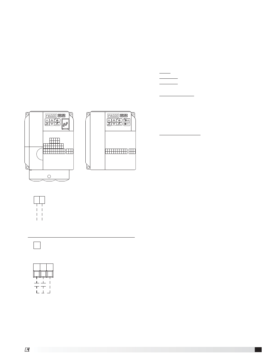
FOR CONTINUOUS 60Hz OPERATION JUMPER TERMINALS A1 AND +V.
WIRED TO A1 (+) AND AC (COMMON)
0-10 VDC CONTROL SIGNAL (BY OTHERS)
10 VDC=60 Hz
0 VDC=30 Hz
A1 AC
FOR ONE 0-10 SIGNAL, WIRE TO DRIVES IN PARALLEL
OPTION 2 - MULTI SPEED CONTROL
S5
S4
SC
NEITHER S4 OR S5 CONTACT CLOSED
DRIVE SPEED = 60 Hz.
DRIVE SPEED = 40 Hz.
S4 TO SC CONTACT CLOSED (BY OTHERS)
S5 TO SC CONTACT CLOSED (BY OTHERS)
DRIVE SPEED = 30 Hz.
TO CHANGE THE FACTORY SET Hz CHANGE THE FOLLOWING PARAMETERS.
PARAMETER A1-01 CHANGE TO 2
PARAMETER d1-02 FOR NEW 40Hz SETTING
PARAMETER d1-01 FOR NEW 60Hz SETTING
PARAMETER d1-03 FOR NEW 30Hz SETTING
PARAMETER A1-01 CHANGE TO 0
USER TO PROVIDE CONTACTS AND ISOLATION
AS REQUIRED
SEE VFD INSTALLATION MANUAL FOR MORE DETAIL
MA MB MC
RP
H1
SC
HC
S7
S6
S5
S4
S3
S2
S1
MP
AC
AM
AC
+V
A2
A1
PC
P2
P1
IG
S-
S+
R-
R+
V1000
MA MB MC
AC
AM
AC
+V
A1
SC
S5
S4
S3
S2
S1
J1000