Temperature calibration, Low fire start time adjustment, Sensitivity adjustment – Greenheck Maxitrol Series 44 User Manual
Page 7
Note: All electronic components are pre-calibrated to a base
resistance. This permits field replacement without upsetting
system calibration.
Minimum Discharge Air Temperature
1. Install a thermometer or other temperature measuring
device at a point adjacent to the tip
of the TS144.
2. Connect a wire jumper between
terminals #4 and #5. Be sure
minimum temperature setting is at
least ten degrees higher than outdoor
temperature.
3. Turn the calibrating potentiometer
(A) until the reading of the
thermometer adjacent to the
TS144 agrees with the minimum
setting of the Discharge Air
Temperature Selector. Clockwise
rotation increases temperature
(A1044L model adjusted from blue
side).
4. Remove jumper.
Maximum Discharge Air Temperature
1. Install a thermometer or other temperature measuring
device at a point adjacent to the tip of the TS144.
2. Disconnect wires from terminals #4 & #5. Connect 12K
resistor across terminals #4 & #5.
7
3. Turn the calibrating potentiometer (B), until the reading
of the thermometer adjacent to the TS144 agrees with
the maximum setting of the Discharge Air Temperature
Selector. Clockwise rotation increases temperature
(A1044L1 model adjusted from blue side). Be sure
temperature setting does not exceed the design
temperature rise of the heater.
4. Remove resistor and reconnect
wires.
Space Temperature
1. Install a thermometer or other
temperature measuring device at a
point adjacent to the T244 or the
TS244. Set the T244 or the TD244
(whichever is used) for the desired
room temperature. Because of the
large space being heated, wait at
least one half hour* to make certain
adjustment is needed.
2. If the temperature reading is
different from the temperature setting,
turn (C) clockwise for an increase in
space temperature and counterclockwise for a decrease in
temperature. Each increment on adjustment C is
approximately 2.5 degrees (A1044L1 model adjusted from
blue side). After an adjustment has been made, give the
room temperature at least one half hour* to settle out
before rechecking.
* One half hour is only a time estimate. Longer or shorter
periods may be required for the temperature to stabilize.
Be sure space temperature is stabilized before attempting
calibration!
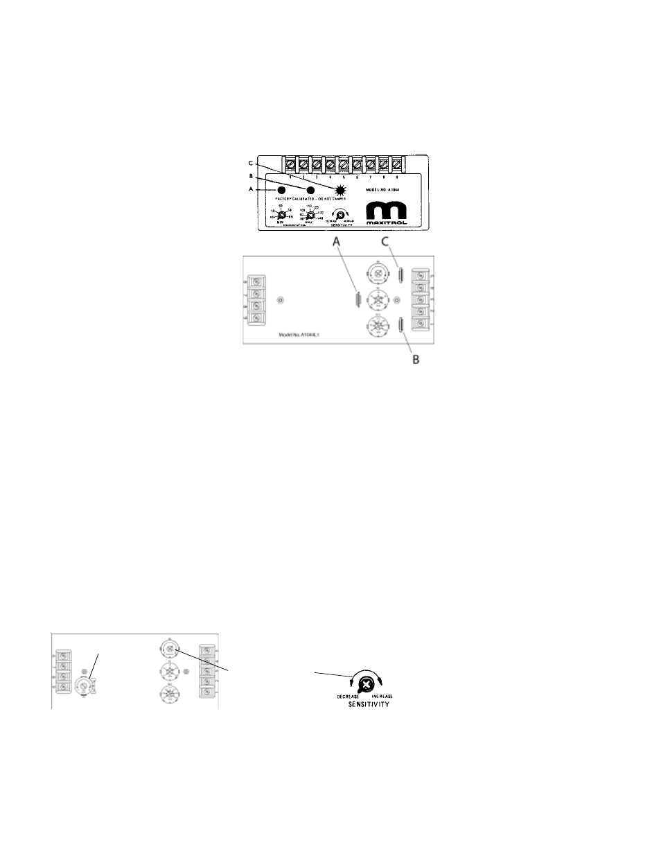
Temperature Calibration
Sensitivity adjustment
Time delay
potentiometer
On A1044L1 (CL1, DL1, EL1) amplifiers, the low fire start
duration is adjustable from approximately 0-30 seconds,
and begins timing after the amplifier has been energized.
High fire is delayed, and the M/MR valve remains in the
low fire setting position during the delay time period.
Use a small screwdriver to adjust the time delay
potentiometer.
Turn clockwise (+) to increase low fire start duration, and
counter-clockwise (-) to decrease low fire start duration.
Low Fire Start Time Adjustment
A1044L1 (CL1, DL1, EL1)
cover removed
A1044 (C, D, E)
model amplifier
Sensitivity Adjustment
The sensitivity control will allow the user to control the
response of the system. Caution should be exercised in
the use of this adjustment. Under normal usage the
pointer should be located on the mark of the label.
If hunting is encountered (rapid oscillation), rotating the
sensitivity control counterclockwise may dampen the
oscillation, stabilizing the flame.
DO NOT adjust unless
necessary, because
decreasing the sensitivity will
increase the temperature
"DROOP" of the system.