Preliminary circuit analysis – Greenheck Maxitrol Series 44 User Manual
Page 6
6
MT1-12/TS144
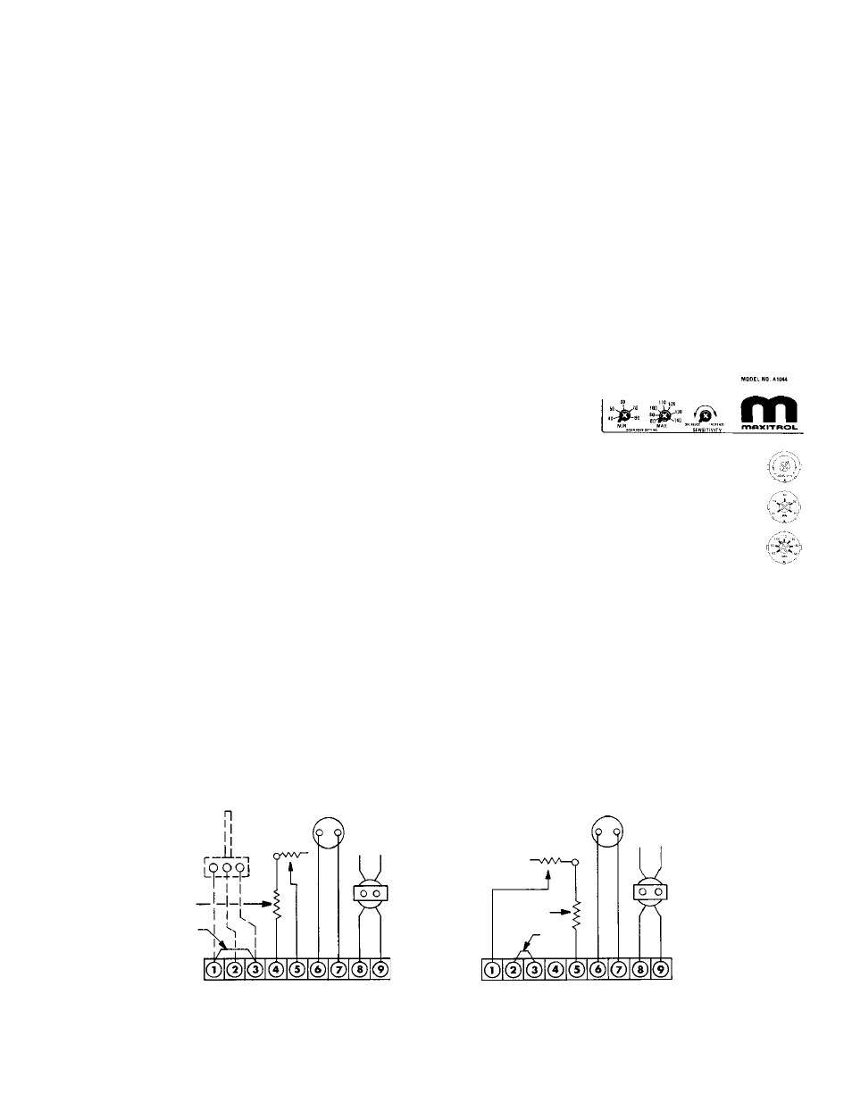
10K TEST
POT
JUMPER
VALVE
24V20VA
TRANS.
RESISTOR
2K
10K TEST POT
VALVE
14V20VA
TRANS.
RESISTOR
2K
JUMPER
Preliminary Circuit Analysis
(Terminal locations shown for A1044 [and C, D, E] model amplifiers.
A1044L1 [and CL1, DL1, EL1] model terminal blocks 1-5 and 6-9 are at opposite ends of the board)
Figure 2
Figure 1
This Preliminary Circuit Analysis will provide identification
of faulty components, improper wiring or calibration, and
other difficulties when used with the tabulated Field
Service Checklist (pages 4 & 5).
Note: All voltages and resistance readings are
approximate.
Section I
1. Wire the system (per Figure 1 below).
2. Connect a DC voltmeter to amplifier terminals #6 & #7.
3. Turn the Test-Potentiometer to minimum resistance.
(2,000 ohms). The DC voltage should read 0 volts.
4. Turn the Test-Potentiometer slowly to maximum
resistance (12,000 ohms). The DC voltage should
gradually increase to at least 18 volts.
If proper voltages are observed continue on with
Section II.
If proper voltages are not observed, the problem is
identified with the Amplifier, the 24-volt AC power
supply, or the circuit connected to terminals #6 & #7.
Section II
1. Turn power OFF, wire system (per Figure 2 below), turn
power ON.
2. Turn Test-Potentiometer to minimum resistance, the
voltage should be 0 volts.
3. Turn Test-Potentiometer slowly to maximum
resistance, the DC voltage should gradually increase to
at least 18 volts.
If proper voltages are observed in both Sections I & II,
the amplifier is satisfactory.
If proper voltages are not observed, continue testing to
identify the difficulty. Faults may be identified with the
amplifier, the 24V power supply, or the circuit
connected to terminals #6 & #7. See Field Service
Checklist.
Section III
1. Observe burner flames and/or burner pressure as Test-
Potentiometer is turned through full range. Note: From
0-5 volts, heater should be at by-pass or low, 5-15 volts,
heater should respond with various input rates; beyond
15 volts, heater is at maximum input.
If proper operation is observed, continue procedure to
check operation of sensing and selecting components.
If proper operation is not observed, see Field Service
Checklist to test M or MR valves and connecting wiring.
Section IV
1. With proper voltages observed thus far and modulator
responding correctly, wire the system (see Figure 1
below), except have TS144 connected in place of
jumper. Set MIN temperature selector at least 10° F
above outdoor temperature. Set MAX
temperature selector
at mid-range. Heater
is now under control
by the
TS144 Discharge Air Monitor.
2. Turn Test-Potentiometer to maximum resistance,
delivered air temperature should be per MAX
temperature setting. Turn Test-Potentiometer to
minimum resistance, delivered air temperature
should be per MIN temperature setting.
If proper delivered air temperatures are observed,
the problem is identified with the space
temperature sensing and/or temperature
selecting components and circuits. See Field Service
Checklist.
If proper delivered air temperatures are not observed,
check calibration. See Field Service Checklist.
Section V
1. After test, remove all test equipment and reconnect all
components.
(or)
Model
A1044L1