Valve adjustments, Wiring diagrams – Greenheck Maxitrol Series 44 User Manual
Page 5
5
Valve Adjustments
(See bulletin MT2035 for additional M/MR valve information)
NOTE: Low fire adjustment should be checked whenever the high fire adjustment is changed.
T244
VALVE
TRANS.
TD244
TS244
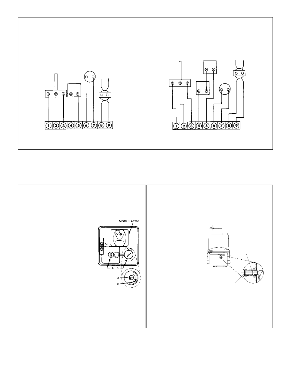
Wiring Diagrams
TRANS.
TS144
MT1-12
VALVE
Amplifier with Selectrastat
Amplifier with remote temperature sensor and
separate temperature selector
TS144
MT1-12
MR 212 VALVE
High Fire Manifold Adjustments:
1. Disconnect wires from amplifier terminal #2 & #4.
This causes the valve to go to continuous high fire.
2. Remove seal cap (A), and turn
regulator pressure adjusting
screw to obtain desired manifold
pressure. (Clockwise rotation
increases pressure.)
3. Reconnect the wires to amplifier
terminal #2 & #4.
NOTE: If low fire bypass is on
maximum, the desired high fire
outlet pressure may not be
achieved.
Low Fire or Bypass Adjustments:
1. Disconnect wire from amplifier terminal
#8, this causes valve to go to continuous low fire.
2. Remove cap (B), and loosen lock screw (C). Turn (D)
to desired low fire adjustment. (Clockwise rotation
reduces minimum flow rate.)
3. Tighten set screw (C), replace cap (B) and reconnect
wire to amplifier terminal #8.
M411, 511, 611 VALVE
High Fire Manifold Adjustments:
1. Disconnect wires from amplifier terminal #2 & #4, this
causes the valve to go to continuous high fire.
2. Adjust the upstream pressure regulator to obtain the
desired manifold
pressure
(7" w.c. maximum).
3. Reconnect the wires
to amplifier terminal
#2 & #4.
Low Fire or Bypass
Adjustments:
1. Disconnect wire from
amplifier terminal #8,
this causes the valve
to go to continuous low fire.
2. Remove cap (A), and turn adjusting screw (B) to
desired low fire adjustment. (Clockwise rotation
reduces minimum flow rate.)
3. Replace cap (A), and reconnect wire to amplifier
terminal #8.
A
B
(Terminal locations shown for A1044 [and C, D, E] model amplifiers.
A1044L1 [and CL1, DL1, EL1] model terminal blocks 1-5 and 6-9 are at opposite ends of the board)