Greenheck IGK (472084) User Manual
Page 3
3
Model IGK Make-Up Air
®
Table of Contents
Installation
Clearance to Combustibles/Service Clearances . 3
Unit Arrangement DB . . . . . . . . . . . . . . . . . . . . . . 4
Weatherhood . . . . . . . . . . . . . . . . . . . . . . . . . . . . . 4
Electrical Wiring . . . . . . . . . . . . . . . . . . . . . . . . . . 5
Gas Piping . . . . . . . . . . . . . . . . . . . . . . . . . . . . . . . 6
Start-Up
Blower . . . . . . . . . . . . . . . . . . . . . . . . . . . . . . . . .7-8
Furnace – All Units . . . . . . . . . . . . . . . . . . . . . . . . 9
2:1 Staged . . . . . . . . . . . . . . . . . . . . . . 9
Operation
Furnace - 2:1 Staged . . . . . . . . . . . . . . . . . . . . . 10
Troubleshooting
Blower . . . . . . . . . . . . . . . . . . . . . . . . . . . . . . . . . 11
Motor Overamps / Too Much Airflow . . . . . . . . . 12
Excessive Noise or Vibration . . . . . . . . . . . . . . . 13
Insufficient Airflow . . . . . . . . . . . . . . . . . . . . . . . . 14
Furnace – 2:1 Staged . . . . . . . . . . . . . . . . . . . . . 15
Maintenance
Routine . . . . . . . . . . . . . . . . . . . . . . . . . . . . . .16-17
Fall . . . . . . . . . . . . . . . . . . . . . . . . . . . . . . . . . . . . 17
Reference
Vent Connections . . . . . . . . . . . . . . . . . . . . . . . . 18
Typical Gas Train Layout . . . . . . . . . . . . . . . . . . . 18
Control Center Layout . . . . . . . . . . . . . . . . . . . . 18
Performance Table . . . . . . . . . . . . . . . . . . . . . . . 18
Control Flow Diagram . . . . . . . . . . . . . . . . . . . . . 19
Wiring Diagrams . . . . . . . . . . . . . . . . . . . . . . .20-21
Maintenance Start-Up List . . . . . . . . . . . . . . . . . 22
Maintenance Log . . . . . . . . . . . . . . . . . . . . . . . . 23
Warranty . . . . . . . . . . . . . . . . . . . . . . . . .Backcover
Indirect Gas Fired Unit Installations
Units are listed for installation in the United States and
Canada
• Installation of gas fired duct furnaces must conform
with local building codes. In the absence of local
codes, installation must conform to the National
Fuel Gas code, ANSI Z223.1 or in Canada, CAN/
CGA-B149 installation codes.
• All electrical wiring must be in accordance with
the regulation of the National Electric Code, ANSI/
NFPA-70.
• Unit is approved for installation downstream from
refrigeration units. In these conditions, condensate
could form in the duct furnace and provision must be
made to dispose of the condensate.
2. Rotate the fan wheel(s) by hand and assure no
parts are rubbing.
3. After storage period, purge grease before putting
fan into service.
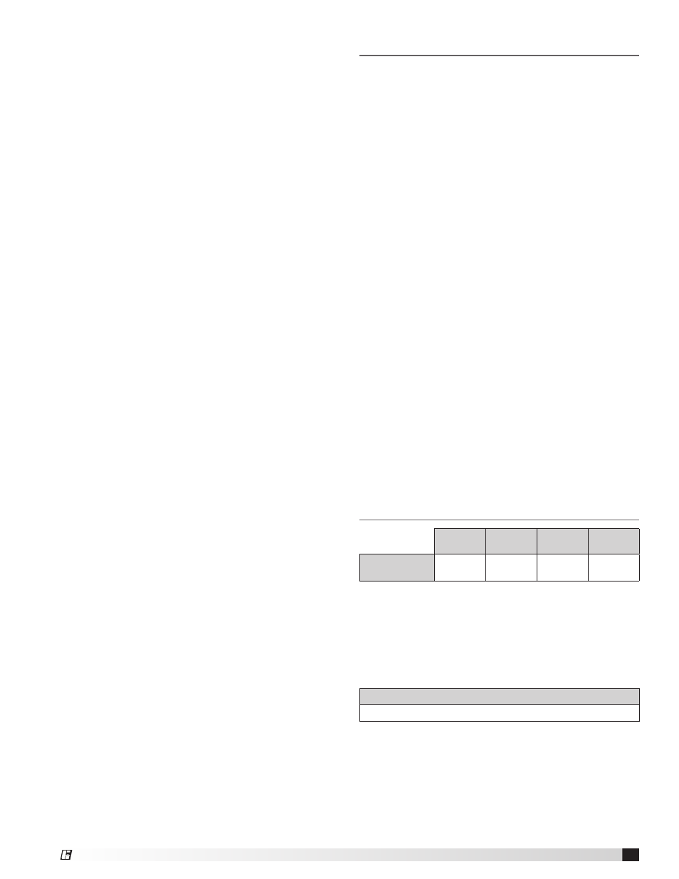
Clearance to Combustibles /
Service Clearances
Floor
Top
Sides
Flue
Outlet
Indirect Fired
Units*
0 inches
(0 mm)
0 inches
(0 mm)
0 inches
(0 mm)
42 inches
(1067 mm)
Clearance to combustibles is defined as the minimum
distance required between the heater and adjacent
combustible surfaces to ensure the adjacent surface’s
temperature does not exceed 90 degrees above the
ambient temperature.
*Reference venting guidelines for combustion blower
clearances.
Recommended Minimum Service Clearances
42 inches (1067 mm)
around the sides and ends of the unit*
Clearances for component removal may be greater
than the service clearances listed.
*Unit access side is determined by looking into the intake in the
direction of airflow.