Electrical installation, Main control power, Caution – Greenheck Fire Ready Hood - GRRS User Manual
Page 12
12
Fire Ready Hood
Main Control Power
1. Determine mounting location of the appliance
disconnect (contactor box and/or gas valve) and
mounting bracket, if not already done.
2. Run factory-provided wire from junction box
through the wall to the appliance disconnect,
unless ClockBox option is provided. For electrical
installation information regarding the ClockBox, refer
to page 16. Wire the factory-provided 110 VAC main
power connection to a 15 amp rated circuit.
3. If the hood unit is to be linked to a fire alarm system,
accommodations for those wires will need to be
made at this time as well. Refer to fire alarm electrical
installation information on page 14.
CAUTION
Electrical installation should be performed by a
licensed electrician. Installation should be performed
according to all applicable codes and regulations. Shut
off power at the main breaker to prevent electrical
shock when accessing electrical connections.
All field installation and wiring of electrical equipment
must be done to meet NEC and local codes
Electrical Installation
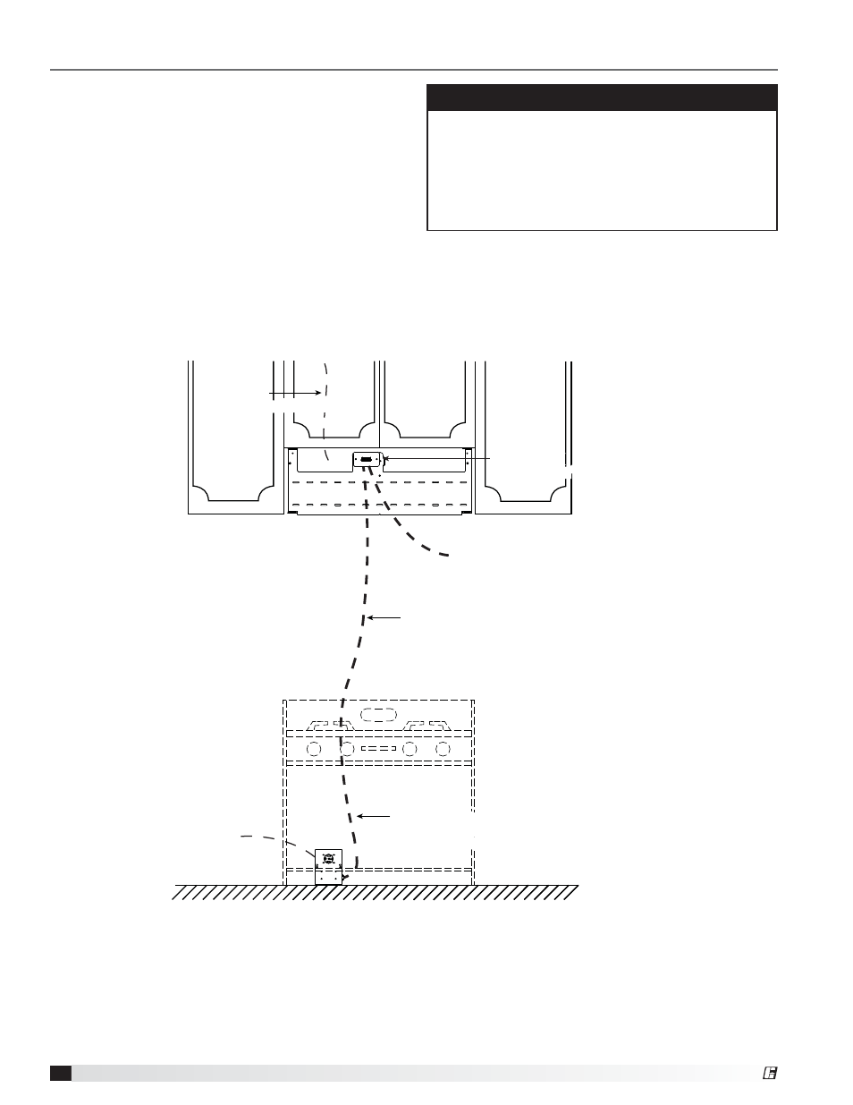
Range Supply Line
208-220 VAC 50A max
supplied by others
Hood Supply 110-120 VAC 15A
Metal clad wire from 110-120 VAC supply line
12/2 8 ft length, marked with red tape
supplied by Greenheck
Run metal clad wire from junction box on mounting
plate to power disconnect box through wall
Metal clad wire from 110-120 VAC supply line
14/2 8 ft length, marked with black tape
supplied by Greenheck
Junction Box
with Connector
Junction Box
with Connector
Alarm Wire(s)
NO/NC Local and Remote Alarm
by others
Alarm Wire(s)
NO/NC Local and Remote Alarm
by others
Power disconnect mounted flush to wall
50A 250V NEMA 14-50 receptacle
supplied by Greenheck
Power disconnect mounted flush to wall
50A 250V NEMA 14-50 receptacle
supplied by Greenheck
®