Controller display, Wiring the controller, Powering the controller – Greenheck AMD Series Dampers (474014) User Manual
Page 5: Connecting the pressure transducer, Connecting the damper actuator, Connecting the flow (or position) setpoint signal, Connecting to the flow output signal, Override mode
5
Where:
C = Voltage Output Signal (VDC)
Q = Real-time Airflow (cfm)
V max = Maximum Velocity as specified at the time the unit was ordered (fpm)
A = Face Area of the Damper (ft2)
Note that Vmax and A are found on the label affixed to the AMD/AMS next to the transducer (see Label 2)
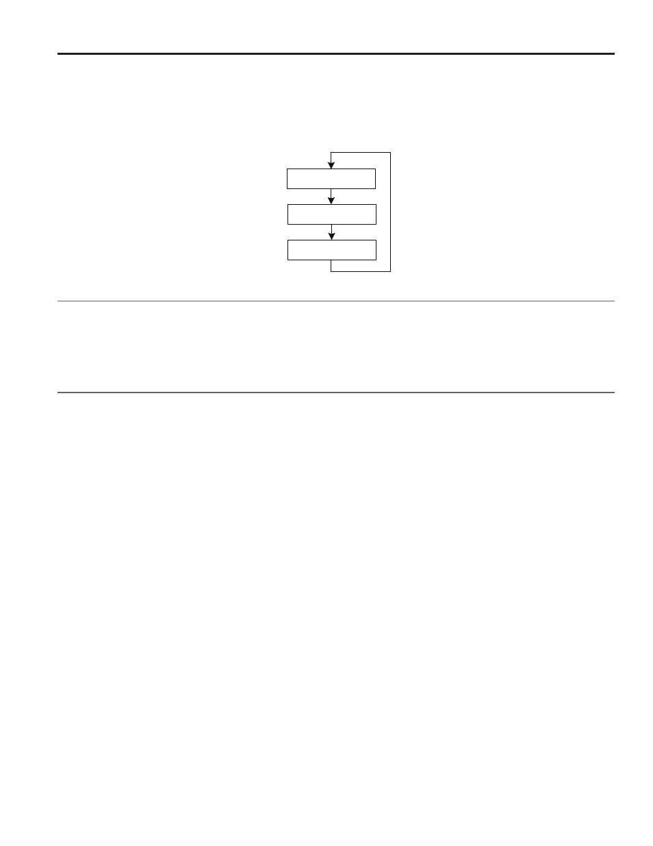
Controller Display
The controller has a two line backlit LCD display. By using the up and down arrows on the controller’s cover the display can
be toggled to show one of three sets of data:
• Top Screen: Real-Time CFM and CFM Setpoint
• Middle Screen: Real-Time Velocity (fpm) and Velocity Setpoint
• Bottom Screen: Real-Time Differential Pressure Measurement and Actuator Position
Wiring the Controller
The basic wiring of the controller is shown below in Figure 2. The controller’s three terminal blocks can be accessed by
opening the cover of the enclosure.
Powering the Controller
The controller is powered by applying electrical power to the “Power In” terminal block. The controller can run off of 24 VAC
+/- 20% 50/60 Hz ; 24 VDC +/- 10%.
Connecting the Pressure Transducer
The second terminal block is labeled “Remote Sensor” and is used to connect the pressure transducer. The three terminals
from the Remote Sensor block connect directly to the pressure transducer as shown in Figure 2. The controller supplies the
transducer with its power and reads the pressure signal.
Connecting the Damper Actuator
The actuator can be powered either by the same power supply as the controller (as shown in Figure 2) or by running a
separate power supply to terminals 4 and 5 of the factory supplied terminal block on the AMD/AMS. In addition, the “Control
Out” from the controller (terminal 7) must be run to terminal 6 on AMD/AMS terminal block.
Connecting the Flow (or position) Setpoint Signal
Connect the 0-10 VDC or 2-10 VDC flow (or position) setpoint to the controller’s terminals 1 and 3. The controller’s terminal 1,
labeled Remote Setpoint, is the positive terminal and the controller’s terminal 3 is the negative terminal.
Connecting to the Flow Output Signal
Connecting to controller terminals 6 and 3 allows the user to read the 0-10 VDC or 2-10 VDC flow output that is proportional
to the cfm measured by the AMD/AMS. To convert the voltage signal to cfm see the section above on Controller’s Analog
Output Proportional to Real-Time Airflow.
Override Mode
See the full Vari-Green constant volume controller installation and operation manual for a description of the override feature.
The override feature can be activated by closing the contacts of an external relay across terminals 2 and 3 (or by simply
putting a jumper wire across them).
XXXXX CFM
Setpt XXXXX CFM
X.XX in WC
Act XX.X% Open
XXXX FPM
Setpt XXXX FPM
Setup and Operation for AMS and AMD Series With Factory Supplied Controller cont...