Electrical guidelines – Greenheck AMD Series Dampers (474014) User Manual
Page 3
3
SAFETY DANGER !
Electrical input may be needed for this
equipment. This work should be performed
by a qualified electrician.
Electrical Guidelines
SAFETY CAUTION !
Verify power requirements before wiring actuator.
Greenheck is not responsible for any damage to, or
failure of the unit caused by incorrect field wiring.
Electrical and/or pneumatic connections to damper actuators should be made in accordance with wiring and piping
diagrams developed in compliance with applicable codes, ordinances and regulations.
Connect electrical connection to terminal strip as shown on drawing (see figure 1).
Setup and Operation for AMS and AMD Series Without Factory Supplied Controller
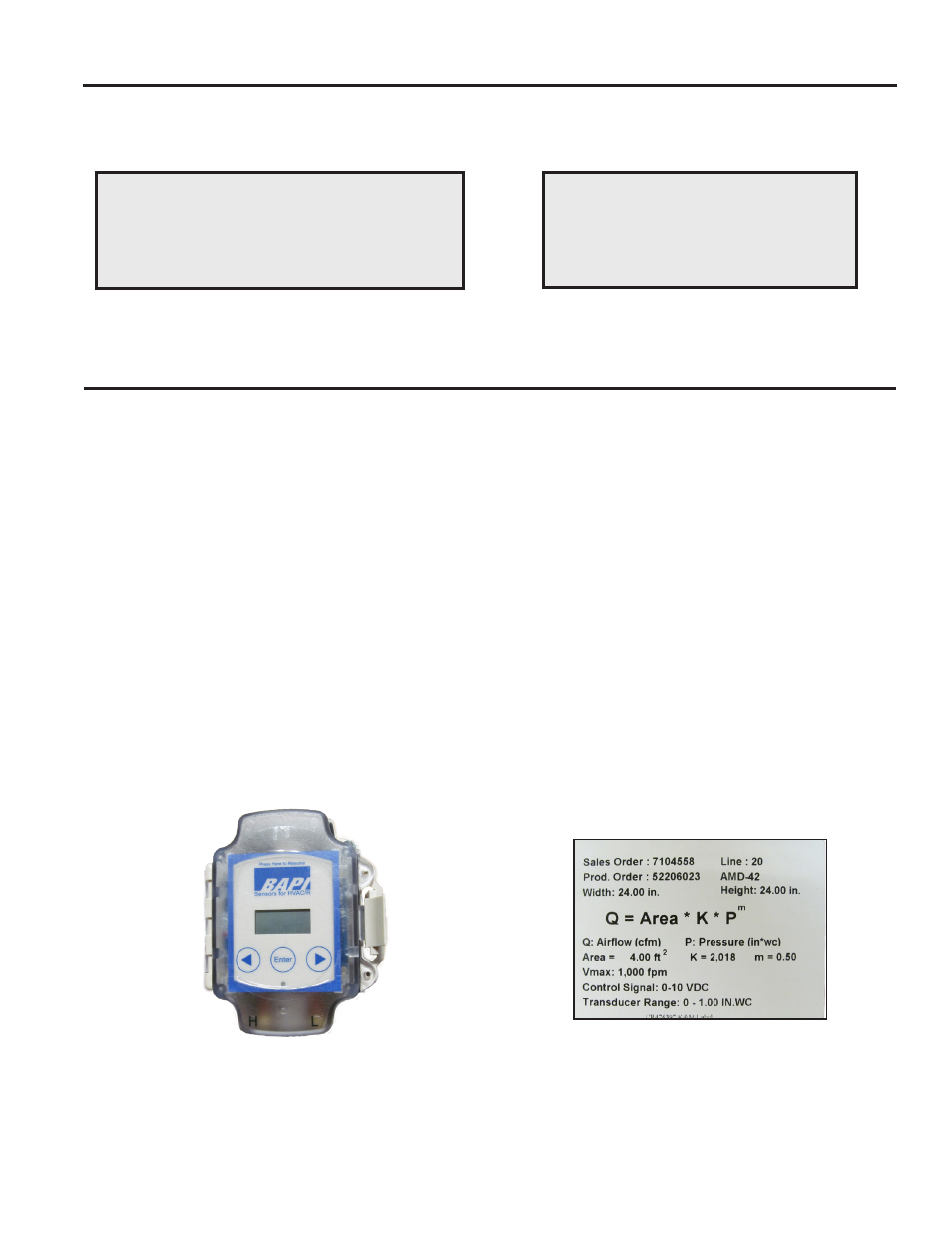
Label 1: AMD/AMS Label
Each AMD and AMS is shipped with a highly accurate pressure transducer (+/- 0.25% of range) that results in optimal airflow
measurement accuracy (see Figure 1).The pressure transducer outputs a 0-10 VDC signal that is proportional to the pressure
measured by the airflow station. The high pressure limit of the transducer is set at the factory to optimize the resolution of
the reading. The selection is based on the maximum velocity of the application that was selected at the time the unit was
ordered. The selected transducer range is listed on a label affixed to the AMD or AMS (see example label below). Using
the high pressure limit of the transducer and the voltage output of the transducer the real-time pressure reading can be
calculated using the formula:
Ptransducer = (Transducer Output Voltage) * (High Pressure Limit of Transducer) / 10
Formula 1
The pressure reading of the transducer can then be used to calculate the volumetric flow rate going through the AMS or AMD
using the formula:
CFM = Damper Area*K*( Ptransducer)m
Formula 2
The K & m values are damper specific constants that are listed on the label. The area of the damper is also listed on the
label.
Figure 1: BAPI transducer