Zone pressure touch (zpt) sensor - standard range – Greenheck BAPI Zone Pressure Touch (ZPT) Sensor User Manual
Page 2
32215_ins_ZPT_SR_NT.pdf
Building Automation Products, Inc., 750 North Royal Avenue, Gays Mills, WI 54631 USA
Tel:+1-608-735-4800 • Fax+1-608-735-4804 • E-mail:[email protected] • Web:www.bapihvac.com
Zone Pressure Touch (ZPT) Sensor - Standard Range
Installation and Operation Instructions
rev. 05/09/2014
Specifications subject to change without notice.
2 of 5
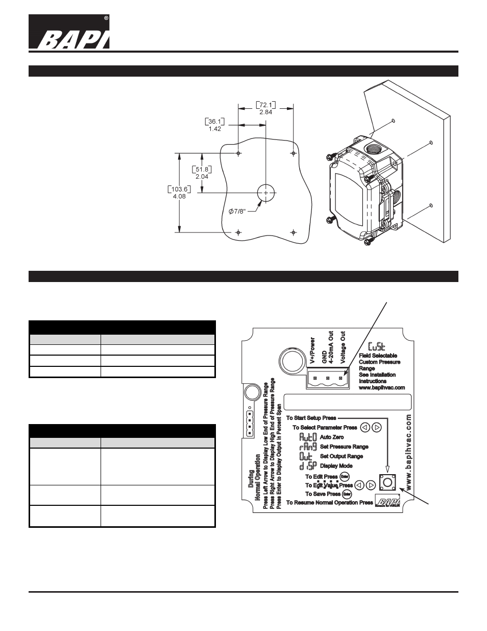
Mounting
Attach the unit to its mounting
surface with four #10 screws
through the holes in the
mounting feet. The preferred
mounting orientation is with the
pressure ports facing down.
Note: Remove Blue Dust Shields
from pressure ports before
use. Push tubing onto the port
nipple. Avoid kinks and holes in
the tubing or accuracy will be
affected.
Note: BAPI recommends using
#10 screws that require 5/32”
pilot holes
Note: Do not mount to a vibrating
Surface
Fig 3: Mounting Screws Location
Fig 2: Mounting Hole Pattern
Wiring Termination
Current Loop Connection
The ZPT unit requires DC voltage for 4 to 20 mA
current loop output, which is “two-wire” operation.
Voltage Output Connection
The ZPT unit allows AC or DC voltage for voltage
output, which is “three-wire” operation.
Terminal
Function
V+/Power
7 to 40 VDC
GND/4 to 20mA Out
4 to 20 mA Signal Output
Voltage Out
Not used
Current Loop Output Connection
Terminal
Function
7 to 40 VDC or 18 to 32 VAC
(for 0 to 5 or 1 to 5 VDC Output)
13 to 40 VDC or 18 to 32 VAC
(for 0 to 10 or 2 to 10 VDC Output)
GND/4 to 20mA Out
To controller Ground
[GND or Common]
Voltage Out
Voltage Output, Pressure Signal,
referenced to GND
V+/Power
Voltage Output Connection
NOTE: The connectors use a rising block screw terminal to hold the wires. It is possible for the block to be in a
partially up position allowing the wire to be inserted under the block. Be sure that the connector screws are turned
fully counterclockwise before inserting the wire. Lightly tug on each wire after tightening to verify proper termination.
Fig 4: Wiring Terminals Inside Enclosure Cover
Setup
Start
Button
Wiring Terminals
Note: Wiring plug removed for
clarity. Wiring plug shown in Fig 1.