Chapter 2 installation instructions – Foxconn 915P7MC-S User Manual
Page 25
Chapter 2 Installation Instructions
18
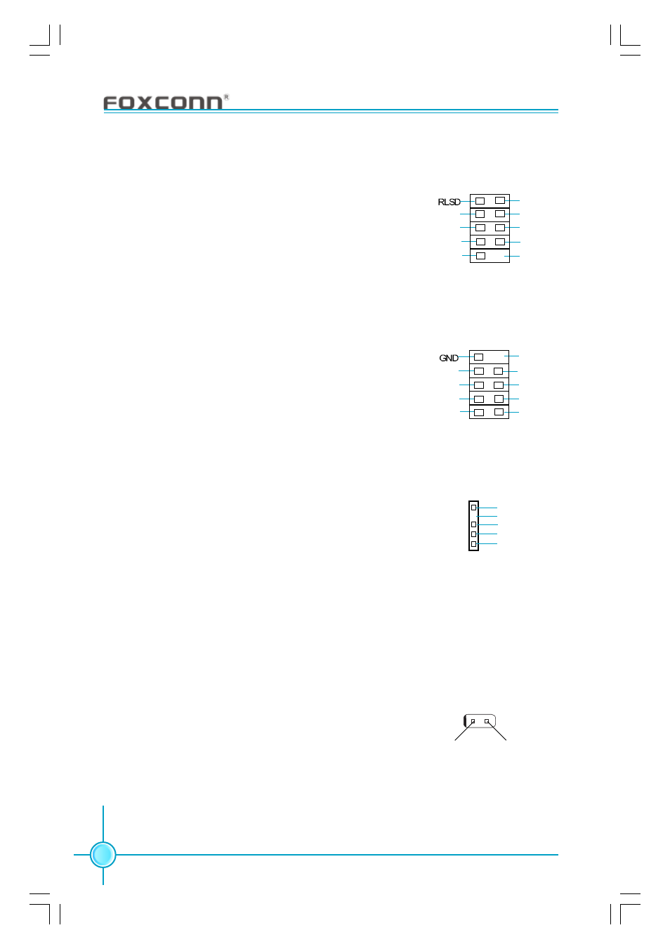
Addtional COM Header: COM2
This motherboard provides an additional serial COM
header for your machine.
Connect one side of a switching cable to the header,
then attach the serial COM device to the other side of
the cable.
SOUT
GND
RI#
DTR#
DSR#
SIN
9
10
1
2
CTS#
RTS#
1394 Header:
F_1394
(optional)
The 1394 expansion cable can be connected to either
the front (provided that the front panel of your chassis
is equipped with the appropriate interface) or real
panel of the chassis.
1
2
GND
+12V
TPB -
TPA -
+12V
TPB +
GND
TPA +
Empty
F_1394
9
10
IrDA Header: IR
This header supports wireless transmitting and receiv-
ing device. Before using this function, configure the
settings of IR Mode from the “Integrated Peripherals”
section of the CMOS Setup.
COM2
IR
1
+5V
GND
IRRX
IRTX
Empty
Chassis Intruder Header: INTR
The connector connects to the chassis security switch on the case. The system
can detect the chasis intrusion through the status of this connector. If the con-
nector has been closed once, the system will send a message. To utilize this
function, set “Case Open Warning” to “Enabled” in the “PC Health Status” sec-
tion of the CMOS Setup. Save and exit, then boot the operating system once to
make sure this function takes effect.
INTR
1 INTRUDERJ
2 GND
Empty