Buswitch, With f – Flowserve BUSwitch User Manual
Page 9
AXAIM020-01
(AUTO-48)
3/03
Page 9 of 16
© 2003, Flowserve Corporation, Printed in U.S.A.
BUSwitch
™
with F
OUNDATION
®
Fieldbus Protocol
Installation, Operating and Maintenance Instructions
Flowserve Corporation
1350 N. Mountain Springs Parkway
1978 Foreman Dr.
Flow Control Division
Springville, Utah 84663-3004
Cookeville, TN 38501
www.flowserve.com
Phone: 801 489 8611
Phone: 931 432 4021
Transducer Block
The Transducer Block (TB) provides the link between
standard function blocks (DO-1, DO-2, DI-1, & DI-2)
and the sensors and piezo/coil actuators within the
BUSwitch
™
device. It tracks number of valve strokes.
The TB also provides some configuration flexibility.
This section details those parameters affecting the
function and configuration of the BUSwitch
™
device.
This discussion includes all operational aspects
of the function blocks as well. A complete list of
TB parameters follows at the end of the section.
Complete function block parameter lists are
provided in Appendices A and B.
Pneumatic Actuator Operation – Single Coil,
Fail Open or Fail Closed
For operation requiring a consistent fail position
(either open or closed), select the “Single Coil”
TB.OPERATION parameter. One DO block (DO-1)
is used. The TB reads DO-1 OUT_D Value and
energizes both the OPEN (P6) and CLOSE (P5)
terminals as shown in the Single Coil Truth Table.
To reverse the actuator fail mode for double acting
actuators, reverse ports 2 and 4. To reverse spring-
return actuators, actuator modification is necessary.
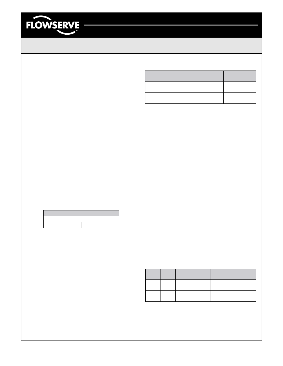
Single Coil Truth Table
When in Auto mode, DO1.OUT_D follows the SP_D
Value. If the user wishes to invert the above truth
table relative to SP_D, change the function block
IO_OPTS parameter to “Invert.” This will energize the
coil on an SP_D Discrete 0 and de-energize on an
SP_D Discrete 1. This toggle has the same effect
when “dual coil” mode is selected; it is necessary to
select “Invert” for both DO blocks.
Pneumatic Actuator Operation – Dual Coil,
Fail in Last Position
Select the “Dual Coil” TB.OPERATION parameter.
Dual Coil Operation uses both DO1.OUT_D and
DO2.OUT_D block parameters configured in an
interlocking manner. For valve movement to take
place, the OUT_D parameters must take on opposite
values as shown in the next table.
Dual Coil Truth Table
Referring to Figure 2, energizing the “OPEN” termi-
nals will provide air to Port 4 and energizing the
“CLOSE” terminals will provide air to Port 2. To
reverse the valve operation, either reverse the
solenoid valve wires on P5 and P6, or reverse the
actuator tubing connections on Port 2 and 4.
The TB.OUTPUT_CONFIGURATION parameter
selects whether solenoid pilot elements stay
energized or become de-energized after the valve
reaches its desired position. If the “Pulse” option
is selected, the elements will de-energize after
the length of time selected in the TB.TIME_OUT
parameter. The “Constant” setting maintains
element voltage until new DO-1 and DO-2 OUT_D
values are selected.
Valve Position Monitoring and Reporting
The BUSwitch
™
TB monitors the status of two limit
switches. SW1 is the upper switch and is set to trip
when the valve reaches the closed position. SW2 is
the lower switch and is set to trip when the valve is
open. The TB.SOLENOIDE_CLOSED parameter
displays SW1 status as False when not tripped and
True when tripped. TB.SOLENOIDE_OPENED
parameter displays SW2 status the same way.
The TB provides limit switch status to the READ-
BACK_D parameters of DO-1 and DO-2 respectively
per the following truth table.
Truth Table for READBACK_D Values
F
OUNDATION
®
Fieldbus DO blocks write the READ-
BACK_D value to the PV_D variable within each
block. PV_D may then be linked to the BKCAL_OUT
variable. Figure 6 shows a schematic of a DO block
illustrating this feature.
DO1.OUT_D
OPEN/CLOSE
De-energized
Energized
1
0
DO1
OUT_D
DO2
OUT_D
OPEN
CLOSE
0
0
0
No Change
No Change
1
Energized
De-energized
1
1
1
No Change
No Change
0
De-energized
Energized
SW1 SW2
DO-1
RDBK
DO-2
RDBK
Meaning
A
A
1
1
Improper switch adj.
A
A
O
1
0
Actuator CLOSED
O
0
1
Actuator OPENED
O
O
0
0
Actuator is moving
A = Activated or Tripped, O = Open or Not Tripped