Buswitch, With f, Oundation – Flowserve BUSwitch User Manual
Page 10
AXAIM020-01
(AUTO-48)
3/03
Page 10 of 16
© 2003, Flowserve Corporation, Printed in U.S.A.
BUSwitch
™
with F
OUNDATION
®
Fieldbus Protocol
Installation, Operating and Maintenance Instructions
Flowserve Corporation
1350 N. Mountain Springs Parkway
1978 Foreman Dr.
Flow Control Division
Springville, Utah 84663-3004
Cookeville, TN 38501
www.flowserve.com
Phone: 801 489 8611
Phone: 931 432 4021
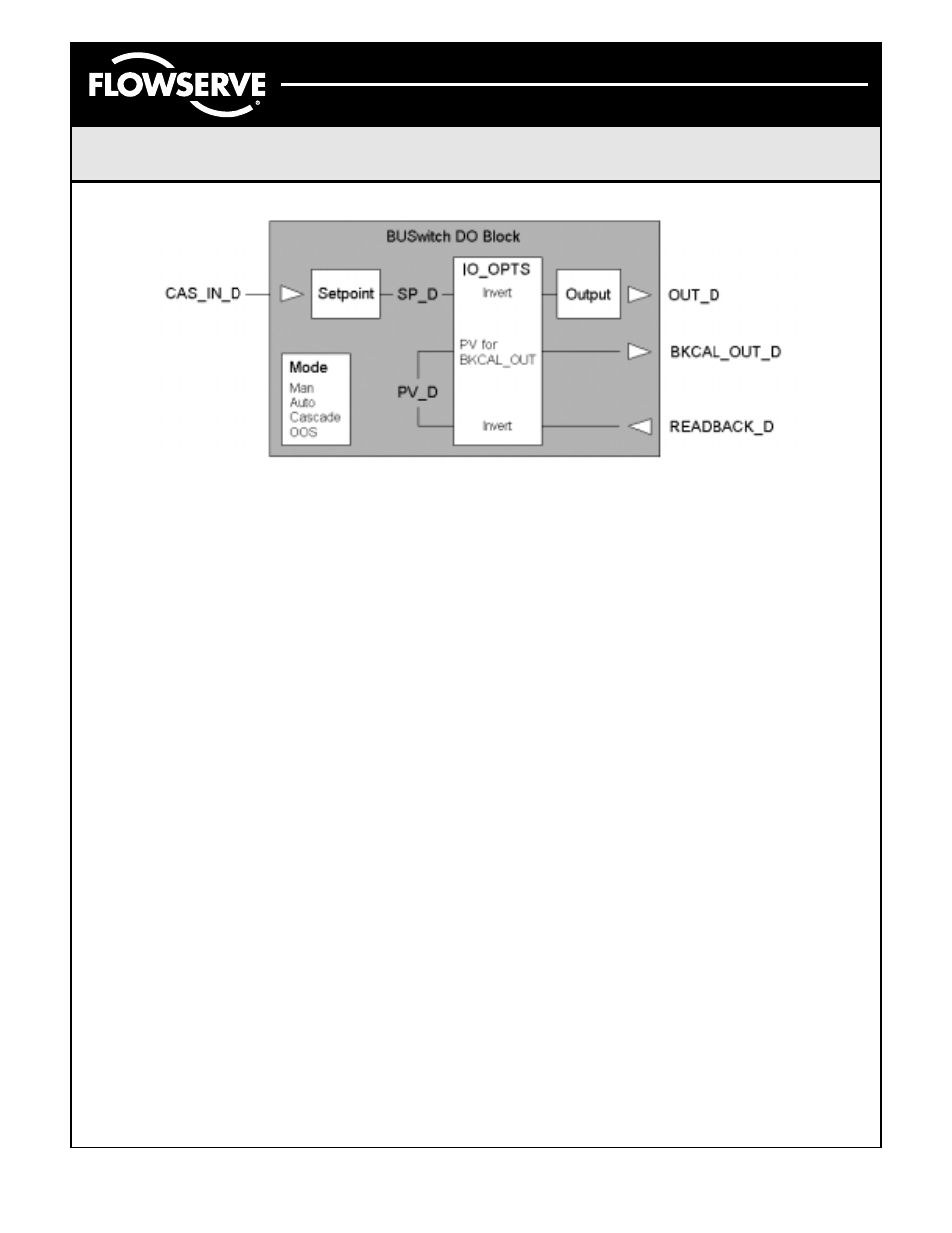
To link DO.PV_D to DO.BKCAL_OUT, configure
the IO_OPTS for the desired block to “PV for
BKCAL_OUT.” Note: This action prevents the use
of “Invert” as an IO Option. Then, link BKCAL_OUT
to the BKCAL_IN of the function block sending the
CAS_IN_D signal.
Auxiliary Dry Contact Input
The BUSwitch
™
TB also monitors continuity across
terminals P4. This status is seen in the external alarm
parameter and in the OUT_D of DI-2. DI-2.OUT_D
will read Discrete 1 when no continuity exists and the
“Normally Closed” J1 and J2 jumpers are selected.
When contact is made in this jumper mode, the out-
put changes to Discrete 0.
To reverse the outputs, change the J1 and J2 settings
to “Normally Open.” Refer to Figures 3 and 4 for the
jumper settings.
Odometer Function
TB Parameter ODOMETER reports the number of
open-closed and closed-open transitions. It may be
reset using the RESET_ODOMETER parameter.
Simply write a “True” value to this parameter to reset.
Valve Stroke Time Out Function
The BUSwitch
™
times each valve stroke and
reports the time from the move command until the
appropriate position switch is tripped. The stroke
time is displayed in the transducer block parameter
“TRANSITION TIME.” If the “TRANSITION TIME” is
greater than the value entered in “TIME-OUT,” an
alarm is generated. This alarm is displayed in the
transducer block parameter “TRANSITION-ALARM”
and is also sent to the DI-1 block “OUT-D.” This is
a “linkable” input and can be used to alter process
control. The alarm will stay present until the “RESET-
TIMEOUT” parameter is set to “TRUE” in the trans-
ducer block.
Additional TB Parameters
Several TB parameters exist to store information
about the valve, actuator and BUSwitch
™
device.
In addition, calibration information may be stored.
Refer to the complete list of BUSwitch
™
TB
parameters starting on page 11 for a description
of these parameters.
Figure 6 – DO Block Schematic