Buswitch, With f – Flowserve BUSwitch User Manual
Page 11
AXAIM020-01
(AUTO-48)
3/03
Page 11 of 16
© 2003, Flowserve Corporation, Printed in U.S.A.
BUSwitch
™
with F
OUNDATION
®
Fieldbus Protocol
Installation, Operating and Maintenance Instructions
Flowserve Corporation
1350 N. Mountain Springs Parkway
1978 Foreman Dr.
Flow Control Division
Springville, Utah 84663-3004
Cookeville, TN 38501
www.flowserve.com
Phone: 801 489 8611
Phone: 931 432 4021
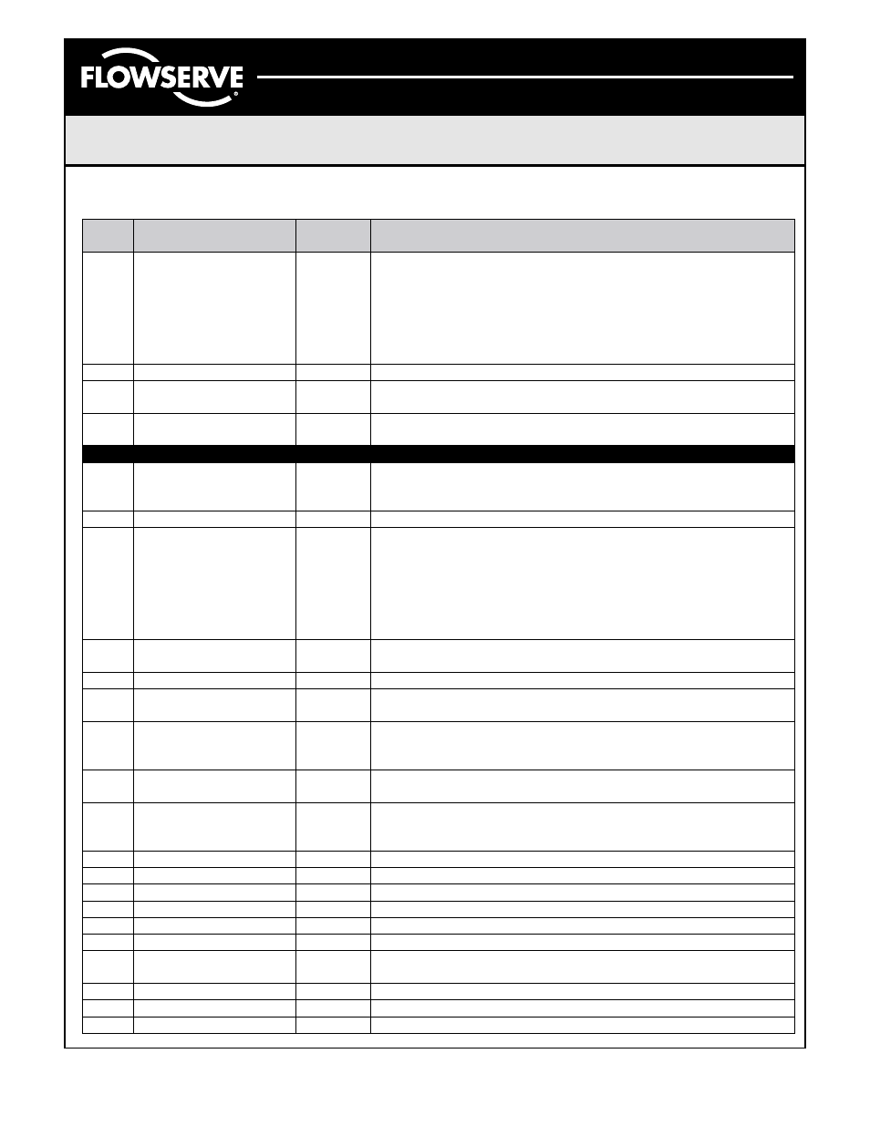
Rel.
Index
Parameter
Factory
Default
Description
1
ST_REV
The revision level of the static data associated with the function
block. To support tracking changes in static parameter attributes,
the associated block’s static revision parameter will be
incremented each time a static parameter attribute value is
changed. Also, the associated block’s static revision parameter
may be incremented if a static parameter attribute is written but
the value is not changed.
2
TAG_DESC
The user description of the intended application of the block.
3
STRATEGY
The strategy field can be used to identify grouping of blocks. This
data is not checked or processed by the block.
4
ALERT_KEY
The identification number of the plant unit. This information may
be used in the host for sorting alarms, etc.
5
MODE_BLK
Auto
The actual, target, permitted, and normal modes of the block.
6
BLOCK_ERR
This parameter reflects the error status associated with the
hardware or software components associated with a block. It is a
bit string, so that multiple errors may be shown.
7
UPDATE_EVT
This alert is generated by any change to the static data.
8
BLOCK_ALM
The block alarm is used for all configuration, hardware, and
connection failure or system problems in the block. The cause of
the alert is entered in the sub-code field. The first alert to become
active will set the Active status in the Status attribute. As soon as
the Unreported status is cleared by the alert reporting task,
another block alert may be reported without clearing the Active
status, if the sub-code has changed.
9
T RANSDUCER_DIREC
TORY
A directory that specifies the number and starting indices of the
transducers in the transducer block.
10
TRANSDUCER_TYPE
Identifies the transducer that follows.
11
XD_ERROR
One of the error codes defined in section 4.8 of the FF-903
document on the XD_ERROR and Block Alarm sub-codes.
12
COLLECTION_DIREC
TORY
A directory that specifies the number, starting indices, and DD
Item IDs of the data collections in each transducer within a
transducer block.
13
FINAL_VALUE_D
The requested valve position and status written by a discrete
Function Block.
14
ACT_FAIL_ACTIN
Specifies the final failure position of the actuator as defined in
section 4.6 of the FF-903 document on the Actuator Failure
Actions.
15
ACT_MAN_ID
4607055
The BUSwitch manufacturer identification number.
16
ACT_MODEL_NUM
The actuator model number.
17
ACT_SN
The actuator serial number.
18
VALVE_MAN_ID
The valve manufacturer identification number.
19
VALVE_MODEL_NUM
The valve model number.
20
VALVE_SN
The valve serial number.
21
VALVE_TYPE
The type of the valve as defined in section 4.7 of the FF-903
document on the Valve Type.
22
XD_CAL_LOC
The location of last calibration.
23
XD_CAL_DATE
Date of the last calibration.
24
XD_CAL_WHO
Name of the person responsible for last calibration.
Transducer Block Parameters