Automax logix 3200iq digital positioner – Flowserve Logix 3200IQ Digital Positioner User Manual
Page 7
Flowserve Corporation
1350 N. Mountain Springs Parkway
1978 Foreman Dr.
Flow Control Division
Springville, Utah 84663-3004
Cookville, TN 38501
www.flowserve.com
Phone: 801 489 2233
Phone: 931 432 4021
FCD AXAIM3200-00 9/04
Page: 7 of 32
© 2004, Flowserve Corporation, Printed in USA
Automax Logix 3200IQ Digital Positioner
Installation, Operation and Maintenance Instructions
NOTE: The Logix 3200IQ positioner carries an
intrinsically safe barrier rating of 100 mA. Input
currents should not exceed 100 mA.
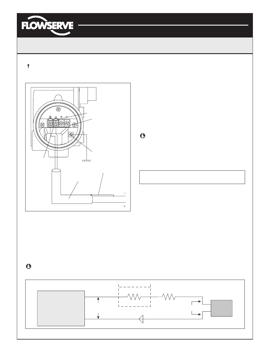
Figure 9: Field Termination
Grounding Screw
The green grounding screw, located inside the termination
cap, should be used to provide the unit with an adequate
and reliable earth ground reference. This ground should
be tied to the same ground as the electrical conduit.
Additionally, the electrical conduit should be earth
grounded at both ends of its run.
WARNING: The green grounding screw must not be
used to terminate signal shield wires.
Compliance Voltage (See Figure 10)
Output compliance voltage refers to the voltage limit that
can be provided by the current source. A current loop
system consists of the current source, wiring resistance,
barrier resistance (if present), and the Logix 3200IQ
positioner impedance. The Logix 3200IQ digital positioner
requires that the current loop system allows for a 10.0
VDC drop across the positioner at maximum loop current.
The 10.0 VDC drop across the Logix 3200IQ positioner
terminals is generated by the positioner from the 4-20 mA
loop current input. The actual voltage at the terminals
varies from 9.8 to 10.0 VDC depending on the current mA
signal, HART communications and ambient temperature.
WARNING: Never connect a voltage source directly
across the positioner terminals. This could cause
permanent circuit board damage.
Determine if the loop will support the Logix 3200IQ digital
positioner by performing the following calculation.
Equation 1
Voltage = Compliance Voltage (@Current
max
) –
Current
max
• (R
barrier
+R
wire
)
The calculated voltage must be greater than 10 VDC in
order to safely support the Logix 3200IQ digital
positioner.
Example:
DCS Compliance Voltage = 19 VDC
R
barrier
= 300
Ω
R
wire
= 25
Ω
Current
max
= 20 mA
Voltage = 19 VDC – 0.020 A • (300
Ω
+ 25
Ω
) = 12.5 VDC
The voltage 12.5 VDC is greater than the required
10.0 VDC; therefore, this system will support the Logix
3200IQ digital positioner. The Logix 3200IQ positioner
has a worst case input resistance equivalent to 500
Ω
at a 20 mA input current.
ANALOG
OUTPUT
HART
4-20 mA INPUT
Shielded Cable
4-20 mA Current Source
Connect Shield at Source
Ground 4-20 mA Current Source
Housing EARTH
Terminal
4-20 mA Feedback
Terminals (Optional)
HART Terminals
Field
Terminators
Current
Source
Logix
3200IQ
If Present
R
Barrier
Current
Compliance
Voltage
R
Wire
10 VDC
+
–
Figure 10: Compliance Voltage